Nissan Almera Tino V10 (2001 year). Manual - part 159
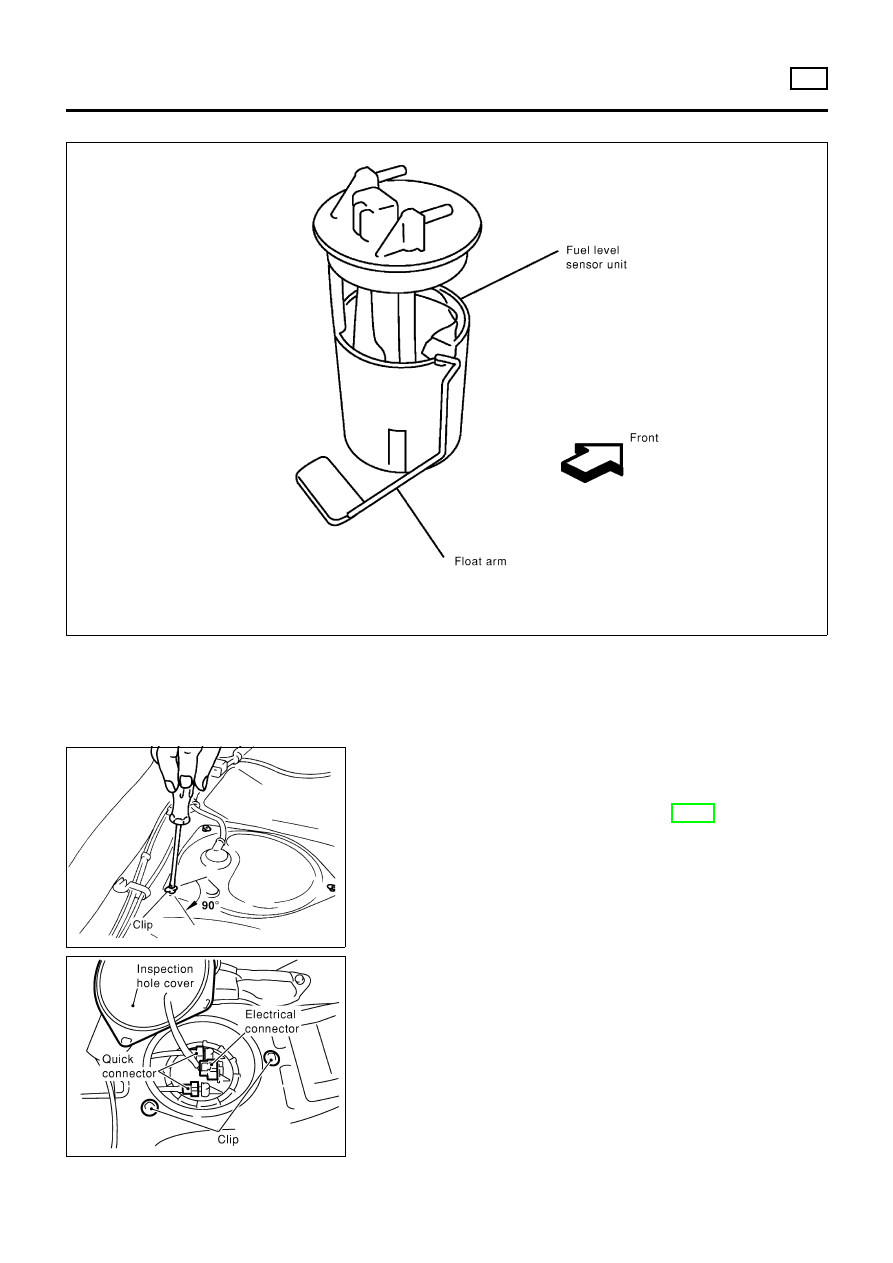
Fuel Level Sensor Unit
NLFE0032
NFE074
JFE613A
REMOVAL
NLFE0032S01
1.
Disconnect battery ground cable.
2.
Open fuel filler lid and filler cap.
3.
Remove rear seat cushion. Refer to BT-49, “Removal and
Installation”.
4.
Remove inspection hole cover under the rear seat.
SFE639A
5.
Disconnect electrical connector.
6.
Disconnect the quick connectors.
+
For disconnect of quick connectors, refer to step 7. of “Fuel
Tank Removal”.
FUEL SYSTEM
YD
Fuel Level Sensor Unit
FE-21