Nissan Almera Tino V10 (2001 year). Manual - part 149
 

  Index      Manuals     Nissan Almera Tino V10 (2001 year) - Service and Repair Manual


Search            copyright infringement  


Content      ..     147      148      149      150     ..


Nissan Almera Tino V10 (2001 year). Manual - part 149


SEM082D

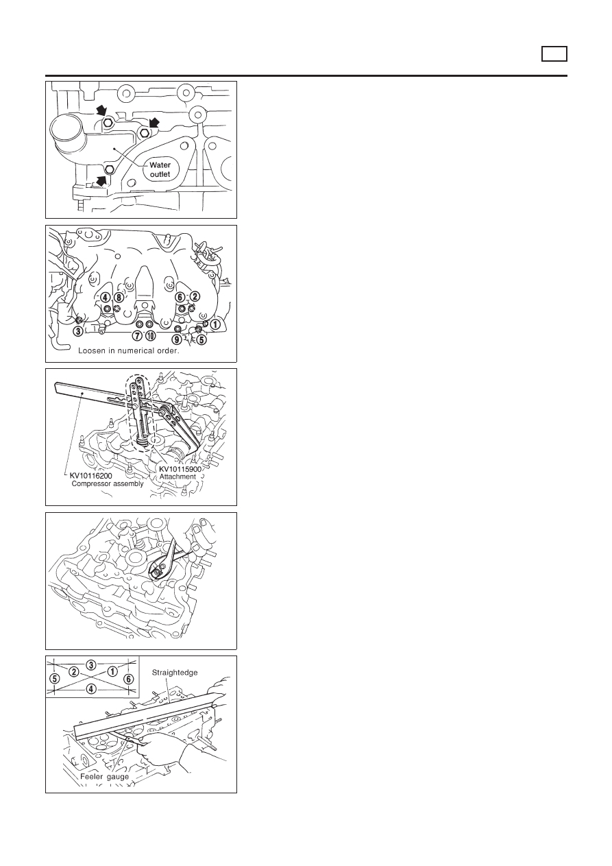
6.

Remove water outlet.

SEM061G

7.

Remove intake manifold with intake manifold collector as
shown.

SEM604E

8.

Remove valve components with Tool. Install camshaft tempo-
rarily.

SEM054G

9.

Remove valve oil seal with a suitable tool.

SEM915F

Inspection

NLEM0133

CYLINDER HEAD DISTORTION

NLEM0133S01

+

Clean mating surface of cylinder head.

+

Use a reliable straightedge and feeler gauge to check the flat-
ness of cylinder head mating surface.

+

Check along six positions shown in figure.

Head surface flatness:

Standard: Less than 0.03 mm (0.0012 in)
Limit: 0.1 mm (0.004 in)

CYLINDER HEAD

SR

Disassembly (Cont’d)

EM-113

If beyond the specified limit, replace or resurface it.
Resurfacing limit:
The limit for cylinder head resurfacing is determined by the
amount of cylinder block resurfacing.
Amount of cylinder head resurfacing is “A”.
Amount of cylinder block resurfacing is “B”.

The maximum limit is as follows:

A + B = 0.2 mm (0.008 in)

After resurfacing cylinder head, check that camshaft rotates freely
by hand. If resistance is felt, replace cylinder head must be
replaced.

Nominal cylinder head height:

136.9 - 137.1 mm (5.390 - 5.398 in)

SEM926C

CAMSHAFT VISUAL CHECK

NLEM0133S02

Check camshaft for scratches, seizure and wear.

CAMSHAFT RUNOUT

NLEM0133S03

1.

Measure camshaft runout at the center journal.

Runout (Total indicator reading):

Standard

Less than 0.02 mm (0.0008 in)

Limit

0.1 mm (0.004 in)

2.

If it exceeds the limit, replace camshaft.

SEM549A

CAMSHAFT CAM HEIGHT

NLEM0133S04

1.

Measure camshaft cam height.

Standard cam height:

Intake

37.775 mm (1.4872 in)

Exhaust

37.404 mm (1.4726 in)

Cam height wear limit:

Intake & Exhaust

0.2 mm (0.008 in)

2.

If wear is beyond the limit, replace camshaft.

CYLINDER HEAD

SR

Inspection (Cont’d)

EM-114

SEM927C

CAMSHAFT JOURNAL CLEARANCE

NLEM0133S05

1.

Install camshaft bracket and tighten bolts. Refer to EM-123.

2.

Measure inner diameter of camshaft bearing.

Standard inner diameter:

28.000 - 28.021 mm (1.1024 - 1.1032 in)

SEM012A

3.

Measure outer diameter of camshaft journal.

Standard outer diameter:

27.950 - 27.970 mm (1.1004 - 1.1012 in)

4.

Calculate camshaft journal clearance.

Camshaft journal clearance = standard inner diameter
– standard outer diameter:

Standard

0.030 - 0.071 mm (0.0012 - 0.0028 in)

Limit

0.15 mm (0.0059 in)

5.

If clearance exceeds the limit, replace camshaft and remea-
sure camshaft journal clearance.

+

If clearance still exceeds the limit after replacing camshaft,
replace cylinder head.

SEM062G

CAMSHAFT END PLAY

NLEM0133S06

1.

Install camshaft in cylinder head. Refer to EM-123.

2.

Measure camshaft end play.

Camshaft end play:

Standard

0.055 - 0.139 mm (0.0022 - 0.0055 in)

Limit

0.20 mm (0.0079 in)

3.

If end play exceeds the limit, replace camshaft and remeasure
camshaft end play.

+

If end play still exceeds the limit after replacing camshaft,
replace cylinder head.

CYLINDER HEAD

SR

Inspection (Cont’d)

EM-115

SEM929C

CAMSHAFT SPROCKET RUNOUT

NLEM0133S07

1.

Install sprocket on camshaft.

2.

Measure camshaft sprocket runout.

Runout (Total indicator reading):

Limit 0.25 mm (0.0098 in)

3.

If it exceeds the limit, replace camshaft sprocket.

SEM003D

VALVE GUIDE CLEARANCE

NLEM0133S08

1.

Measure valve deflection as shown in illustration. (Valve and
valve guide mostly wear in this direction.)

Valve deflection limit (Dial gauge reading):

Intake & Exhaust

0.2 mm (0.008 in)

SEM938C

2.

If it exceeds the limit, check valve to valve guide clearance.

a.

Measure valve stem diameter and valve guide inner diameter.

b.

Calculate valve to valve guide clearance.

Valve to valve guide clearance = valve guide inner
diameter − valve stem diameter:

Standard

Intake 0.020 - 0.053 mm (0.0008 - 0.0021 in)
Exhaust 0.040 - 0.073 mm (0.0016 - 0.0029 in)

Limit

Intake 0.08 mm (0.0031 in)
Exhaust 0.1 mm (0.004 in)

c.

If it exceeds the limit, replace valve and remeasure clearance.

+

If clearance still exceeds the limit after replacing valve, replace
valve guide.

SEM008A

VALVE GUIDE REPLACEMENT

NLEM0133S09

1.

To remove valve guide, heat cylinder head to 110 to 130°C
(230 to 266°F).

CYLINDER HEAD

SR

Inspection (Cont’d)

EM-116

SEM931C

2.

Drive out valve guide with a press [under a 20 kN (2 ton, 2.2
US ton, 2.0 Imp ton) pressure] or hammer and suitable tool.

SEM932C

3.

Ream cylinder head valve guide hole.

Valve guide hole diameter
(for service parts):

Intake & Exhaust

10.175 - 10.196 mm (0.4006 - 0.4014 in)

SEM083D

4.

Heat cylinder head to 110 to 130°C (230 to 266°F) and press
service valve guide into cylinder head.

Projection “L”:

14.0 - 14.2 mm (0.551 - 0.559 in)

SEM932C

5.

Ream valve guide.

Finished size:

Intake & Exhaust

6.000 - 6.018 mm (0.2362 - 0.2369 in)

SEM934C

VALVE SEATS

NLEM0133S10

Check valve seats for pitting at contact surface. Resurface or
replace if excessively worn.

+

Before repairing valve seats, check valve and valve guide
for wear. If they are worn, replace them. Then correct valve
seat.

+

Use both hands to cut uniformly.

CYLINDER HEAD

SR

Inspection (Cont’d)

EM-117

SEM795A

REPLACING VALVE SEAT FOR SERVICE PARTS

NLEM0133S11

1.

Bore out old seat until it collapses. Set machine depth stop so
that boring cannot contact the bottom face of seat recess in
cylinder head.

2.

Ream cylinder head recess.

Reaming bore for service valve seat
Oversize [0.5 mm (0.020 in)]:

Intake 35.500 - 35.516 mm (1.3976 - 1.3983 in)
Exhaust 31.500 - 31.516 mm (1.2402 - 1.2408 in)

Use the valve guide center for reaming to ensure valve seat
will have the correct fit.

SEM008A

3.

Heat cylinder head to 110 to 130°C (230 to 266°F).

4.

Press fit valve seat until it seats on the bottom.

SEM892B

5.

Cut or grind valve seat to the specified dimensions using a
suitable tool. Refer to SDS, EM-150.

6.

After cutting, lap valve seat with abrasive compound.

7.

Check valve seating condition.

Seat face angle “

α

”:

44°53

- 45°07

Contacting width “W”:

Intake

1.385 - 1.401 mm (0.0545 - 0.0552 in)

Exhaust

1.385 - 1.401 mm (0.0545 - 0.0552 in)

CYLINDER HEAD

SR

Inspection (Cont’d)

EM-118

SEM188A

VALVE DIMENSIONS

NLEM0133S12

Check dimensions of each valve. Refer to SDS, EM-147.
When valve head has been worn down to 0.5 mm (0.020 in) in
margin thickness, replace valve.
Grinding allowance for valve stem tip is 0.2 mm (0.008 in) or
less.

SEM288A

VALVE SPRING

NLEM0133S13

Squareness

NLEM0133S1301

1.

Measure dimension “S”.

Out-of-square “S”:

Less than 2.2 mm (0.087 in)

2.

If it exceeds the limit, replace spring.

Free height

Check free height: 49.36 mm (1.9433 in)

EM113

Pressure

NLEM0133S1302

Check valve spring pressure at specified spring height.

Pressure:

Standard

519 - 571 N (52.9 — 58.2 kg, 116.7 — 128.4 lb) at
27 mm (1.06 in)

Limit

More than 501 N (51.1 kg, 112.6 lb) at 27 mm (1.06
in)

If it exceeds the limit, replace spring.

SEM935C

HYDRAULIC LASH ADJUSTER

NLEM0133S17

1.

Check contact and sliding surfaces for wear or score.

SEM936C

2.

Check diameter of lash adjuster.

Outer diameter:

16.980 - 16.993 mm (0.6685 - 0.6690 in)

CYLINDER HEAD

SR

Inspection (Cont’d)

EM-119

SEM084D

3.

Check lash adjuster guide hole diameter.

Inner diameter:

17.000 - 17.020 mm (0.6693 - 0.6701 in)

Standard clearance between lash adjuster and adjuster
guide hole:

0.007 - 0.040 mm (0.0003 - 0.0016 in)

SEM063G

ROCKER ARM, SHIM AND ROCKER ARM GUIDE

NLEM0133S18

Check contact and sliding surfaces of rocker arms, shims and
rocker arm guides for wear or score.

Assembly

NLEM0135

CAUTION:

+

When installing rocker arms, camshaft and oil seal, lubri-
cate contacting surfaces with new engine oil.

+

When tightening cylinder head bolts, camshaft sprocket
bolts and camshaft bracket bolts, lubricate bolt threads
and seat surfaces with new engine oil.

AEM116

+

If a hydraulic lash adjuster is kept on its side, there is a
risk of air entering it. When hydraulic lash adjusters are
removed, stand them straight up or soak them in new
engine oil.

+

Do not disassemble hydraulic lash adjusters.

+

Attach tags to lash adjusters so as not to mix them up.

SEM595D

1.

Install valve component parts.

+

Install valves, noting their identification marks as indi-
cated in the table below.

Identification mark

Intake valve

E71

Exhaust valve

6Y2

CYLINDER HEAD

SR

Inspection (Cont’d)

EM-120

SEM085D

+

Always use new valve oil seal.
Refer to EM-105.

+

Before installing valve oil seal, install valve spring seat.

+

Install valve spring (uneven pitch type) with its narrow
pitched side (paint mark) toward cylinder head side.

+

After installing valve components, use plastic hammer to
lightly tap valve stem tip to assure a proper fit.

SEM093D

2.

Check hydraulic lash adjusters.

a.

Push on the rocker arm above the hydraulic lash adjuster. If it
moves 1 mm (0.04 in) or more, there is air in the high pressure
chamber of hydraulic lash adjuster.
Noise will be emitted from hydraulic lash adjuster if engine is
started without bleeding air.

AEM117

b.

Remove hydraulic lash adjuster and dip in a container filled
with new engine oil. While pushing plunger as shown in figure,
lightly push check ball using a thin rod. Air is completely bled
when plunger no longer moves.

Air cannot be bled from this type of lash adjuster by running
engine.

SEM202D

3.

Install rocker arms, shims, rocker arm guides and hydraulic
lash adjusters.

CAUTION:

Install all parts in their original positions.

SEM364D

4.

Select a suitable shim when replacing any of the following
parts with a new one: Cylinder head, shim, rocker arm guide
and valve seat. Proceed as follows to select the shim of cor-
rect thickness.

a.

Install valve component parts to cylinder head (Except shim).

+

Always replace rocker arm guide with a new one.

CYLINDER HEAD

SR

Assembly (Cont’d)

EM-121

SEM365DA

b.

Remove hydraulic lash adjuster.

c.

Install Tool* into hydraulic lash adjuster fixing hole.
* Tool (KV10115700) is screwed into magnetic stand rod used
with dial gauge.

d.

SEM899D

Make sure that the following parts are installed to the cylinder
head: Valve, valve spring, collet, retainer and rocker arm guide
(except shim). Measure difference (T

1

) between sliding surface

of rocker arm guide and valve stem end on shim side.
When measuring, lightly pull dial indicator rod toward you
to eliminate play in Tool (KV10115700).

SEM096D

e.

Select correct shim.

Shim thickness (T):

T

1

±

0.025 mm (0.0010 in)

+

Shims are available in different thicknesses from 2.800 mm
(0.1102 in) to 3.200 mm (0.1260 in) in increments of 0.025 mm
(0.0010 in).

SEM064G

5.

Install intake manifold with intake manifold collector as shown.

CYLINDER HEAD

SR

Assembly (Cont’d)

EM-122

SEM059GA

6.

Install exhaust manifold.

+

Tighten exhaust manifold bolts in numerical order.

Exhaust manifold:

: 49 - 63 N·m (5.0 - 6.5 kg-m, 37 - 47 ft-lb)

SEM060G

7.

Install EGR volume control valve assembly.

SEM058G

8.

Install EGR tube.

9.

Install exhaust manifold cover.

BEM005

10. Install water outlet.
a.

Remove old liquid gasket from mating surface of water outlet.

+

Also remove old liquid gasket from mating surface of cyl-
inder head.

b.

Apply a continuous bead of liquid gasket to mating surface of
water outlet.

+

Use Genuine RTV silicone sealant part No. 999MP-A7007
or equivalent.

AEM250

Installation

NLEM0136

1.

Before installing cylinder head gasket, apply liquid gasket as
shown in the illustration.

CYLINDER HEAD

SR

Assembly (Cont’d)

EM-123

SEM390G

SEM877A

2.

Install cylinder head completely with intake and exhaust mani-
folds.

+

Apply engine oil to threads and seating surfaces of cylin-
der head bolts before installing them.

+

Be sure to install washers between bolts and cylinder
head.
Cylinder head bolts are tightened by plastic zone tightening
method. Whenever the size difference between d1 and d2
exceeds the limit, replace them with new ones.

Limit (d1 - d2):

0.15 mm (0.0059 in)

+

If reduction of outer diameter appears in a position other than
d2, use it as d2 point.

SEM986C

3.

Tighten cylinder head bolts using the following procedure.

a.

Tighten all bolts to 39 N·m (4.0 kg-m, 29 ft-lb).

b.

Tighten all bolts to 78 N·m (8.0 kg-m, 58 ft-lb).

c.

Loosen all bolts completely.

d.

Tighten all bolts to 39 N·m (4.0 kg-m, 29 ft-lb).

SEM043G

SEM044G

e.

Method A:
Turn all bolts 90 to 95 degrees clockwise with Tool or
suitable angle wrench.
Method B:
If an angle wrench is not available, mark all cylinder head
bolts on the side facing engine front. Then, turn each cyl-
inder head bolt 90 to 95 degrees clockwise.

f.

Turn all bolts another 90 to 95 degrees clockwise.

g.

Ensure that paint mark on each bolt faces the rear of the
engine. (Method B only)

Do not turn any bolt 180 to 190 degrees clockwise all at once.

CYLINDER HEAD

SR

Installation (Cont’d)

EM-124

AEM113

Tightening torque N·m (kg-m, ft-lb)

a.

39 (4.0, 29)

b.

78 (8.0, 58)

c.

0 (0, 0)

d.

39 (4.0, 29)

e.

90 - 95 degrees (90 degrees preferred)

f.

90 - 95 degrees (90 degrees preferred)

SEM037G

4.

Install cylinder head outside bolts.

5.

Install the following water hoses:

+

Water hose for cylinder block.

+

Water hoses for heater.

SEM036G

6.

Install starter motor.

BEM004

7.

Remove old liquid gasket from mating surface of LH camshaft
end bracket.

+

Also remove old liquid gasket from mating surface of cyl-
inder head.

8.

Apply liquid gasket to mating surface of LH camshaft end
bracket as shown in illustration.

+

Use Genuine RTV silicone sealant part No. 999MP-A7007
or equivalent.

SEM045G

9.

Install camshafts, camshaft brackets.

+

Position camshaft.

+

LH camshaft key at about 12 o’clock.

+

RH camshaft key at about 10 o’clock.
Apply new engine oil to bearing and cam surfaces of cam-
shafts before installing them.

CYLINDER HEAD

SR

Installation (Cont’d)

EM-125

SEM098DA

+

Position camshaft brackets as shown in the illustration.
Apply new engine oil to threads and seating surfaces of
camshaft bracket bolts before installing them.

SEM046G

+

Arrange bolts (Size and length).
A: M6 x 53.8 mm (2.12 in)
B: M6 x 37 mm (1.46 in)
C: M8 x 35 mm (1.38 in)

SEM047G

SEM046G

+

Tightening procedure

STEP 1:

RH camshaft

Tighten bolts 9 - 10 in that order then tighten bolts
1 - 8 in numerical order.

: 2 N·m (0.2 kg-m, 17 in-lb)

LH camshaft

Tighten bolts 11 - 12 in that order then tighten
bolts 1 - 10 in numerical order.

: 2 N·m (0.2 kg-m, 17 in-lb)

STEP 2:

Tighten bolts in numerical order.

: 6 N·m (0.6 kg-m, 52 in-lb)

STEP 3:

Tighten bolts in numerical order.
Bolt type A B

: 9.8 - 11.8 N·m (1.0 - 1.2 kg-m, 7.2 - 8.7 ft-lb)

Bolt type C

: 18 - 25 N·m (1.8 - 2.6 kg-m, 13 - 19 ft-lb)

SEM048G

10. Install camshaft sprockets and timing chain on them.

Line up mating marks on timing chain with mating marks
on camshaft sprockets.

CYLINDER HEAD

SR

Installation (Cont’d)

EM-126

SEM049G

+

Lock camshafts as shown in figure and tighten to specified
torque.

: 137 - 157 N·m (14.0 - 16.0 kg-m, 101 - 116 ft-lb)

Apply new engine oil to threads and seating surfaces of cam-
shaft sprocket bolts before installing them.

SEM050G

11. Install distributor.

+

Make sure that position of camshaft is as shown in figure.

SEM033G

+

Make sure that No. 1 piston is set at TDC and that distribu-
tor rotor is set at No. 1 cylinder spark position.

SEM990C

SEM991C

12. Install chain tensioner.
Make sure the camshaft sprockets are tightened completely.
Press cam stopper down and “press-in” sleeve until hook can
be engaged on pin. When tensioner is bolted in position the
hook will release automatically. Make sure arrow “A” points
toward engine front.

CYLINDER HEAD

SR

Installation (Cont’d)

EM-127

SEM066G

13. Install thermostat housing with water pipe.

SEM030G

14. Install intake manifold supports.

BEM006

SEM051G

15. Remove old liquid gasket from mating surfaces of rocker cover

and cylinder head.

16. Apply a continuous bead of liquid gasket to rocker cover gas-

ket and cylinder head as shown in the illustrations.

+

Use Genuine RTV silicone sealant Part No. 999MP-A7007
or equivalent.

CYLINDER HEAD

SR

Installation (Cont’d)

EM-128


Content      ..     147      148      149      150     ..