Nissan Almera Tino V10 (2001 year). Manual - part 147


  Index      Manuals     Nissan Almera Tino V10 (2001 year) - Service and Repair Manual


Search            copyright infringement  


Content      ..     145      146      147      148     ..


Nissan Almera Tino V10 (2001 year). Manual - part 147


Use the table below to help you find the cause of the symptom.
1.

Locate the area where noise occurs.

2.

Confirm the type of noise.

3.

Specify the operating condition of the engine.

4.

Check the specified noise source.

If necessary, repair or replace these parts.

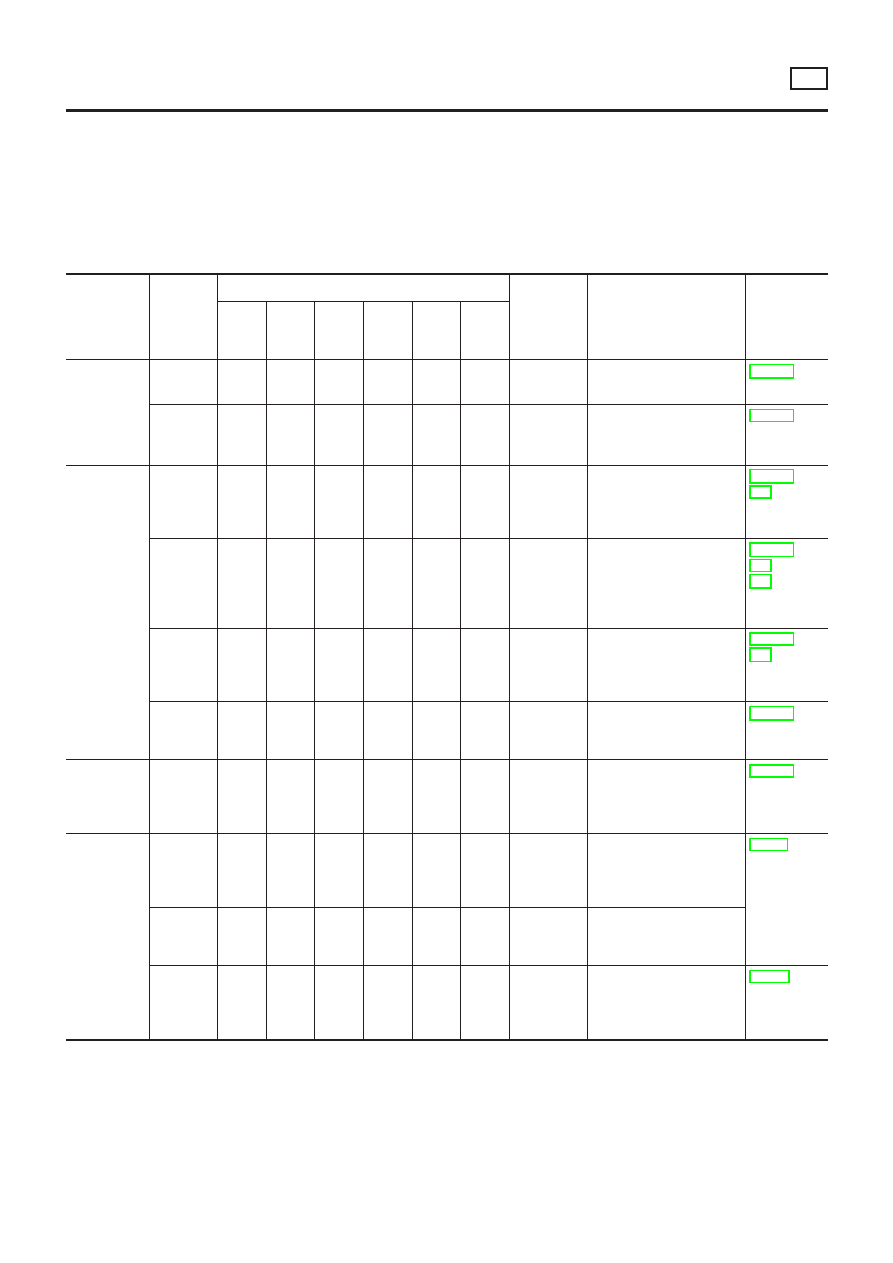
NVH Troubleshooting — Engine Noise

NLEM0116S01

Location of

noise

Type of

noise

Operating condition of engine

Source of

noise

Check item

Reference

page

Before

warm-

up

After

warm-

up

When

start-

ing

When

idling

When

racing

While

driving

Top of
engine
Rocket
cover
Cylinder
head

Ticking or
clicking

C

A

A

B

Rocker
noise

Hydraulic lash adjuster

EM-119

Rattle

C

A

A

B

C

Camshaft
bearing
noise

Camshaft journal clear-
ance
Camshaft runout

EM-115

Crankshaft
pulley
Cylinder
block (Side
of engine)
Oil pan

Slap or
knock

A

B

B

Piston pin
noise

Piston and piston pin
clearance
Connecting rod bushing
clearance

EM-134,
141

Slap or
rap

A

B

B

A

Piston slap
noise

Piston-to-bore clearance
Piston ring side clearance
Piston ring end gap
Connecting rod bend and
torsion

EM-135,
136,
137

Knock

A

B

C

B

B

B

Connecting
rod bearing
noise

Connecting rod bushing
clearance (Small end)
Connecting rod bearing
clearance (Big end)

EM-140,
141

Knock

A

B

A

B

C

Main bear-
ing noise

Main bearing oil clear-
ance
Crankshaft runout

EM-138

Front of
engine
Timing
chain cover

Tapping
or ticking

A

A

B

B

B

Timing
chain and
chain ten-
sioner noise

Timing chain cracks and
wear
Timing chain tensioner
operation

EM-100

Front of
engine

Squeak or
fizzing

A

B

B

C

Other drive
belts (Stick-
ing or slip-
ping)

Drive belts deflection

EM-86,
“Checking
Drive Belts”

Creaking

A

B

A

B

A

B

Other drive
belts (Slip-
ping)

Idler pulley bearing
operation

Squall
Creak

A

B

B

A

B

Water
pump noise

Water pump operation

LC-34,
“Water
Pump
Inspection”

A: Closely related

B: Related

C: Sometimes related

—: Not related

NOISE, VIBRATION AND HARSHNESS (NVH) TROUBLESHOOTING

SR

Commercial Service Tools (Cont’d)

EM-81

Removal and Installation

NLEM0117

NEM351

1.

Oil filler cap

2.

Rocker cover

3.

PCV valve

4.

Distributor

5.

Intake manifold supports

6.

Knock sensor

7.

Oil filter

8.

Oil filter bracket

9.

Water inlet

10. Thermostat housing

11. Water pipe assembly
12. Thermostat
13. Starter motor
14. Power steering oil pump adjusting

bar

15. Power steering oil pump bracket

OUTER COMPONENT PARTS

SR

Removal and Installation

EM-82

NEM378

OUTER COMPONENT PARTS

SR

Removal and Installation (Cont’d)

EM-83

SEM019G

1.

Oil level gauge

2.

Generator adjusting bar

3.

A/C compressor bracket

4.

Alternator bracket

5.

Water outlet

6.

Cylinder block drain plug

7.

Exhaust manifold (With three way
catalyst)

8.

Exhaust manifold cover

9.

Heated oxygen sensor

OUTER COMPONENT PARTS

SR

Removal and Installation (Cont’d)

EM-84

NLEM0118

1.

Warm up engine.

2.

Turn ignition switch OFF.

3.

Release fuel pressure.
Refer to EC-578, “Fuel Pressure Release”.

4.

Remove all spark plugs.

5.

Disconnect distributor coil connector.

SEM973E

SEM387C

6.

Attach a compression tester to No. 1 cylinder.

7.

Depress accelerator pedal fully to keep throttle valve wide
open.

8.

Crank engine and record highest gauge indication.

9.

Repeat the measurement on each cylinder.

+

Always use a fully-charged battery to obtain specified
engine speed.

Compression pressure: kPa (kg/cm

2

, psi)/rpm

Standard

1,275 (13.0, 185)/300

Minimum

1,079 (11.0, 156)/300

Difference limit between cylinders

98 (1.0, 14)/300

10. If compression in one or more cylinders is low:
1)

Pour a small amount of engine oil into cylinders through spark
plug holes.

2)

Retest compression.

+

If adding oil helps compression, piston rings may be worn
or damaged. If so, replace piston rings after checking pis-
ton.

+

If pressure stays low, a valve may be sticking or seating
improperly. Inspect and repair valve and valve seat. Refer
to SDS, EM-150. 
If valve or valve seat is damaged
excessively, replace them.

+

If compression stays low in two cylinders that are next to
each other:

i)

The cylinder head gasket may be leaking, or

ii)

Both cylinders may have valve component damage.
Inspect and repair as necessary.

MEASUREMENT OF COMPRESSION PRESSURE

SR

EM-85

Checking

NLEM0119

SMA266C

1.

Inspect belt for cracks, fraying, wear and oil. If necessary,
replace.

2.

Inspect drive belt deflection or tension at a point on the belt
midway between pulleys.

3.

Turn crankshaft two revolutions and re-check drive belt deflec-
tion or tension.

+

Inspect drive belt deflection or tension when engine is
cold.

+

Adjust if belt deflection exceeds the limit or if belt tension
is not within specifications.

DRIVE BELTS

SR

Checking

EM-86

Deflection adjustment

Unit: mm (in)

Tension adjustment*

Unit: N (kg, lb)

Used belt

New belt

Used belt

New belt

Limit

After adjust-

ment

Limit

After adjust-

ment

Alternator

12 - 13

(0.47 - 0.51)

8 - 9

(0.31 - 0.35)

7 - 8

(0.28 - 0.31)

264

(26.9, 59.3)

493 - 583

(50.3 - 59.5,

110.8 - 131.1)

11720 70J00

11720 70J05

603 - 691

(61.5 - 70.5,

135.6 -

155.3)

652 - 740

(66.5 - 75.5,

146.6 - 166.4)

Air conditioner
compressor

9 (0.35)

5.5 - 6.5

(0.217 - 0.256)

4.5 - 5.5

(0.177 -

0.217)

304

(31.0, 68.3)

534 - 623

(54.5 - 63.5,

120.0 - 140.1)

11920 9F500

11920 9F505

652 - 740

(66.5 - 75.5,

146.6 -

166.4)

838 - 926

(85.5 - 94.5,

188 - 208)

Power steering
oil pump

12 (0.47)

8 - 9

(0.31 - 0.35)

7 - 8

(0.28 - 0.31)

264

(26.9, 59.3)

493 - 583

(50.3 - 59.5,

110.8 - 131.1)

603 - 691

(61.5 - 70.5,

135.6 -

155.3)

603 - 691

(61.5 - 70.5,

135.6 - 155.3)

Applied push-
ing force

98 N (10 kg, 22 lb)

*: If belt tension gauge cannot be installed at check points shown, check drive belt tension at a different location on the belt.

SMA328C

DRIVE BELTS

SR

Checking (Cont’d)

EM-87

NMA006

Changing Air Cleaner Filter

NLEM0120

VISCOUS PAPER TYPE

NLEM0120S01

Unfasten clamps to change air cleaner filter.
The viscous paper type filter does not need cleaning.

AIR CLEANER

SR

Changing Air Cleaner Filter

EM-88

SMA273C

Checking and Changing Spark Plugs

NLEM0121

1.

Disconnect ignition wires from spark plugs at boot. Do not pull
on the wire.

SMA294A

2.

Remove spark plugs with spark plug wrench.

3.

Check insulator for cracks or chips, gasket for damage or dete-
rioration and electrode for wear and burning. If they are exces-
sively worn away, replace with new spark plugs.

Spark plug

Make

NGK

Models with EGR

Models without EGR

Standard type

PFR6G-11

BKR6EY-11

Hot type

PFR5G-11

Cold type

PFR7G-11

Use standard type spark plug for normal condition.
The cold type spark plug is suitable when spark knock may occur
with the standard type spark plug such as:

+

extended highway driving

+

frequent high engine revolution

SMA673B

+

Do not use a wire brush for cleaning.

+

If plug tip is covered with carbon, spark plug cleaner may
be used.

Cleaner air pressure:

Less than 588 kPa (6 kg/cm

2

, 85 psi)

Cleaning time:

Less than 20 seconds

SMA806C

+

Adjusting plug gap is not required.

4.

Check spark plug gap.

Gap: 1.0 - 1.1 mm (0.039 - 0.043 in)

SPARK PLUG

SR

Checking and Changing Spark Plugs

EM-89

5.

Install spark plugs. Reconnect ignition wires according to num-
bers indicated on them.

Spark plug:

: 20 - 29 N·m (2 - 3 kg-m, 14 - 22 ft-lb)

SMA015A

Checking Ignition Leads

NLEM0158

1.

Inspect wires for cracks, damage, burned terminals and for
improper fit.

2.

Measure the resistance of wires and check for intermittent
breaks.

Resistance:

Cylinder No.

Resistance k

[at 25°C (77°F)]

1

Approximately 3.8

2

Approximately 3.5

3

Approximately 2.76

4

Approximately 2.4

For U.K. (Made by Bougicord)

4.48 - 6.72 k

/m (1.365 - 2.048 k

/ft) [at 25°C (77°F)]

If it exceeds the limit, replace the ignition wire with a new one.

SPARK PLUG

SR

Checking and Changing Spark Plugs (Cont’d)

EM-90

Components

NLEM0122

SEM020G

Removal

NLEM0123

1.

Remove engine side cover.

2.

Drain engine oil.

SEM021G

3.

Remove steel oil pan bolts in numerical order.

OIL PAN

SR

Components

EM-91

SEM365E

4. Remove steel oil pan.
a. Insert Tool between aluminum oil pan and steel oil pan.
1) Be careful not to damage aluminum mating surface.

Do not insert screwdriver, or oil pan flange will be dam-
aged.

b. Slide Tool by tapping on the side of the Tool with a hammer.
c. Remove steel oil pan.

SEM045D

5. Remove front exhaust tube. Refer to FE- 23, “EXHAUST SYS-

TEM”.

6. Set a suitable transmission jack under transaxle and lift engine

with engine slinger.

7. Remove center member.

AEM234

8. Remove A/C compressor gussets.

SEM043D

9. Remove rear cover plate.
10. Remove front exhaust tube.

SEM022G

11. Remove aluminum oil pan bolts in numerical order.

OIL PAN 

SR

Removal (Cont’d)

EM-92

SEM506F

12. Remove baffle plate.

SEM023G

13. Remove two engine-to-transaxle bolts and install one of them

into open bolt hole as shown. Tighten installed bolt to separate
aluminum oil pan from cylinder block.

14. Remove aluminum oil pan.

SEM024G

15. Remove the engine-to-transaxle bolts previously installed in

aluminum oil pan.

SEM050D

Installation

NLEM0124

1.

Install aluminum oil pan.

a.

Use a scraper to remove old liquid gasket from mating sur-
faces.

+

Also remove old liquid gasket from mating surfaces of
cylinder block and front cover.

SEM357E

b.

Apply a continuous bead of liquid gasket to mating surface of
aluminum oil pan.

+

Use Genuine RTV silicone sealant part No. 999MP-A7007
or equivalent.

+

Apply to groove on mating surface.

+

Allow 7 mm (0.28 in) clearance around bolt holes.

OIL PAN

SR

Removal (Cont’d)

EM-93

BEM008

+

For areas marked with “

”, apply liquid gasket around the

outer side of the bolt hole as shown.

+

Be sure liquid gasket diameter is 4.0 to 5.0 mm (0.157 to
0.197 in).

+

Attaching should be done within 5 minutes after coating.

SEM025G

c.

Tighten nuts and bolts in numerical order.

Bolts 1 - 16:

: 16 - 19 N·m (1.6 - 1.9 kg-m, 12 - 14 ft-lb)

Bolts 17, 18:

: 6.4 - 7.5 N·m (0.65 - 0.76 kg-m, 56.4 - 66.0 in-lb)

SEM224D

2.

Install the two engine-to-transaxle bolts.
For tightening torque, refer to AT-207, “REMOVAL AND
INSTALLATION”.

3.

Install rear cover plate.

AEM235

4.

Install A/C compressor gussets.

5.

Install center member.

6.

Install front exhaust tube.

7.

Install baffle plate.

SEM026G

8.

Install steel oil pan.

a.

Use a scraper to remove old liquid gasket from mating surface
of steel oil pan.

+

Also remove old liquid gasket from mating surface of alu-
minum oil pan.

OIL PAN

SR

Installation (Cont’d)

EM-94

SEM015E

b.

Apply a continuous bead of liquid gasket to mating surface of
steel oil pan.

+

Use Genuine RTV silicone sealant part No. 999MP-A7007
or equivalent.

+

Apply to groove on mating surface.

+

Allow 7 mm (0.28 in) clearance around bolt hole.

SEM027G

+

Be sure liquid gasket diameter is 4.0 to 5.0 mm (0.157 to
0.197 in).

+

Attaching should be done within 5 minutes after coating.

SEM028G

c.

Tighten bolts in numerical order as shown.

+

Wait at least 30 minutes before refilling engine oil.

OIL PAN

SR

Installation (Cont’d)

EM-95

Components

NLEM0125

YEM007

1.

Cylinder block

2.

Upper chain guide

3.

Intake camshaft sprocket

4.

Chain tensioner

5.

Chain guide

6.

Front cover

7.

Crank pulley

8.

Oil pump spacer

9.

Crankshaft sprocket

10. Chain guide
11. Timing chain
12. Exhaust camshaft sprocket

TIMING CHAIN

SR

Components

EM-96


Content      ..     145      146      147      148     ..