Nissan Almera Tino V10 (2001 year). Manual - part 108
Diagnostic Procedure
NLEC1270
1
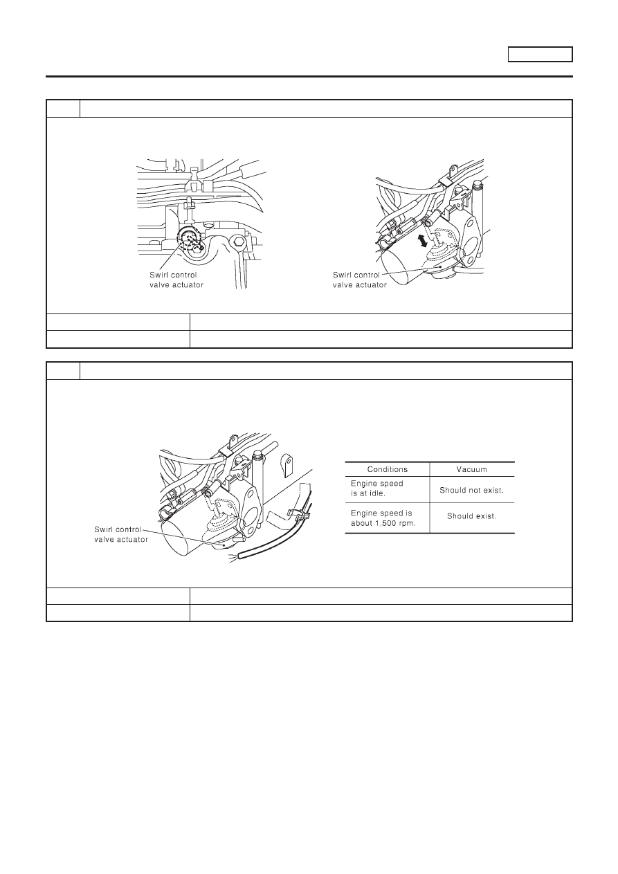
CHECK OVERALL FUNCTION
1. Start engine and warm it up to normal operating temperature.
2. Run engine at idle speed.
3. Make sure that swirl control valve actuator rod moves by revving engine to 1,500 rpm and returning to idle.
SEF873Z
OK or NG
OK
©
INSPECTION END
NG
©
GO TO 2.
2
CHECK VACUUM SOURCE
1. Turn ignition switch “OFF”.
2. Disconnect vacuum hose connected to swirl control valve actuator.
3. Start engine and warm it up to normal operating temperature.
4. Check vacuum hose for vacuum existence under the following conditions.
SEF874Z
OK or NG
OK
©
GO TO 3.
NG
©
GO TO 4.
SWIRL CONTROL VALVE CONTROL SOLENOID VALVE
YD22DDTI
Diagnostic Procedure
EC-1289