Nissan Almera Tino V10 (2001 year). Manual - part 106
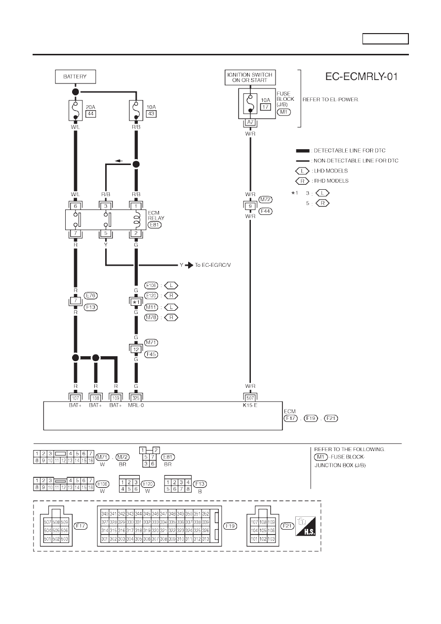
MODELS WITH ECM IN CABIN
NLEC0747S02
YEC864
DTC P1620 ECM RLY
YD22DDTI
Wiring Diagram (Cont’d)
EC-1257
|
|
|
MODELS WITH ECM IN CABIN NLEC0747S02 YEC864 DTC P1620 ECM RLY YD22DDTI Wiring Diagram (Cont’d) EC-1257 |