Nissan Almera Tino V10 (2001 year). Manual - part 96


  Index      Manuals     Nissan Almera Tino V10 (2001 year) - Service and Repair Manual


Search            copyright infringement  


Content      ..     94      95      96      97     ..


Nissan Almera Tino V10 (2001 year). Manual - part 96


Erasing the emission-related diagnostic information using CONSULT-II is easier and quicker than
switching the diagnostic test mode using the data link connector.

SEF252Z

NATS (Nissan Anti-Theft System)

NLEC1265

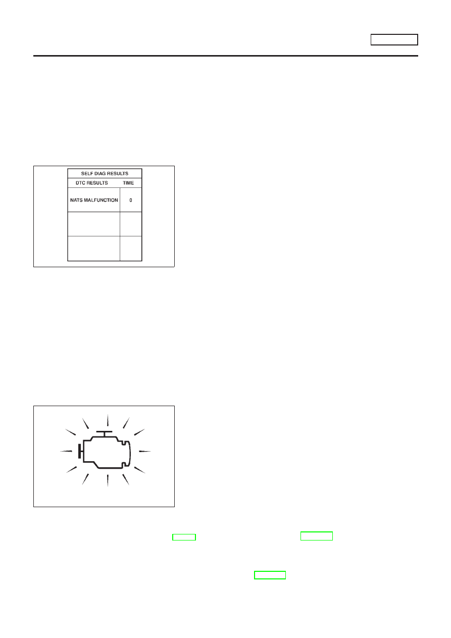
If the security indicator lights up with the ignition switch
in the “ON” position or “NATS MALFUNCTION” is dis-
played on “SELF-DIAG RESULTS” screen, perform self-
diagnostic results mode with CONSULT-II using NATS pro-
gram card. Refer to “NATS (Nissan Anti-Theft System)” in
EL section.

Confirm no self-diagnostic results of NATS is displayed
before touching “ERASE” in “SELF-DIAG RESULTS”
mode with CONSULT-II.

When replacing ECM, initialization of NATS system and
registration of all NATS ignition key IDs must be carried
out with CONSULT-II using NATS program card.
Therefore, be sure to receive all keys from vehicle owner.
Regarding the procedures of NATS initialization and NATS
ignition key ID registration, refer to CONSULT-II operation
manual, NATS.

Malfunction Indicator (MI)

DESCRIPTION

NLEC0628

SAT652J

The MI is located on the instrument panel.
1. The MI will light up when the ignition switch is turned ON without the engine running. This is a bulb check.

If the MI does not light up, refer to EL-10, “WARNING LAMPS” or see EC-1303.

2. When the engine is started, the MI should go off.

If the MI remains on, the on board diagnostic system has detected an engine system malfunction.

If MI illuminates or blinks irregularly after starting engine, water may have accumulated in fuel filter.
Drain water from fuel filter. Refer to “WATER DRAINING”, EC-1094.

ON BOARD DIAGNOSTIC SYSTEM DESCRIPTION 

YD22DDTI

NATS (Nissan Anti-Theft System)

EC-1097

On Board Diagnostic System Function

NLEC0628S01

The on board diagnostic system has the following three functions.

Diagnostic Test
Mode

KEY and ENG.
Status

Function

Explanation of Function

Mode I

Ignition switch in
ON position

Engine stopped

BULB CHECK

This function checks the MI bulb for damage (blown,
open circuit, etc.).
If the MI does not come on, check MI circuit. (See
EC-1303.)

Engine running

MALFUNCTION
WARNING

This is a usual driving condition. When ECM detects a
malfunction, the MI will light up to inform the driver that
a malfunction has been detected.

Mode II

Ignition switch in
ON position

Engine stopped

SELF-DIAGNOSTIC RESULTS

This function allows DTCs to be read.

ON BOARD DIAGNOSTIC SYSTEM DESCRIPTION

YD22DDTI

Malfunction Indicator (MI) (Cont’d)

EC-1098

How to Switch Diagnostic Test Modes

NLEC0628S02

SEF878Y

*1: EC-1303

*2: EC-1098

*3: EC-1303

ON BOARD DIAGNOSTIC SYSTEM DESCRIPTION

YD22DDTI

Malfunction Indicator (MI) (Cont’d)

EC-1099

Diagnostic Test Mode I — Bulb Check

NLEC0628S03

In this mode, the MI on the instrument panel should stay ON. If it remains OFF, check the bulb. Refer to EL-10,
“WARNING LAMPS” or see EC-1303.

Diagnostic Test Mode I — Malfunction Warning

NLEC0628S04

MI Condition

ON When the malfunction is detected or the ECM’s CPU is malfunctioning.

OFF No malfunction.

Diagnostic Test Mode II — Self-diagnostic Results

NLEC0628S05

In this mode, DTC is indicated by the number of blinks of the MI as shown below.

SEF298QA

SEF162PB

Long (0.6 second) blinking indicates the two LH digits of number and short (0.3 second) blinking indicates the
two RH digits of number. For example, the MI blinks 10 times for 6 seconds (0.6 sec x 10 times) and then it
blinks three times for about 1 second (0.3 sec x 3 times). This indicates the DTC “1003”.
In this way, all the detected malfunctions are classified by their DTC numbers. The DTC “0505” refers to no
malfunction. (See TROUBLE DIAGNOSIS — INDEX, EC-1064.)

How to Erase Diagnostic Test Mode II (Self-diagnostic results)

NLEC0628S06

The DTC can be erased from the backup memory in the ECM when the diagnostic test mode is changed from
Diagnostic Test Mode II to Diagnostic Test Mode I. (Refer to “How to Switch Diagnostic Test Modes”, EC-1099.)

If the battery terminal is disconnected, the DTC will be lost from the backup memory within 24
hours.

Be careful not to erase the stored memory before starting trouble diagnoses.

ON BOARD DIAGNOSTIC SYSTEM DESCRIPTION 

YD22DDTI

Malfunction Indicator (MI) (Cont’d)

EC-1100

Relationship Between MI, DTC, CONSULT-II and Driving Patterns

NLEC0628S07

SEF879Y

*1: When a malfunction is detected,

MI will light up.

*2: When the same malfunction is

detected in two consecutive driv-
ing patterns, MI will stay lit up.

*3: MI will go off after vehicle is driven

three times without any malfunc-
tions.

*4: When a malfunction is detected

for the first time, the DTC will be
stored in ECM.

*5: The DTC will not be displayed any

longer after vehicle is driven 40
times without the same malfunc-
tion. (The DTC still remain in
ECM.)

*6: Other screens except SELF-DIAG-

NOSTIC RESULTS & DATA
MONITOR (AUTO TRIG) cannot
display the malfunction. DATA
MONITOR (AUTO TRIG) can dis-
play the malfunction at the
moment it is detected.

ON BOARD DIAGNOSTIC SYSTEM DESCRIPTION

YD22DDTI

Malfunction Indicator (MI) (Cont’d)

EC-1101

SEF378Y

CONSULT-II

NLEC0629

CONSULT-II INSPECTION PROCEDURE

NLEC0629S01

1.

Turn ignition switch OFF.

2.

Connect CONSULT-II to data link connector.
(Data link connector is located under the driver side dash
panel.)

SEF995X

SEF320Y

3.

Turn ignition switch ON.

4.

Touch “START”.

5.

Touch “ENGINE”.

6.

Perform each diagnostic test mode according to each service
procedure.

For further information, see the CONSULT-II Operation
Manual.

ON BOARD DIAGNOSTIC SYSTEM DESCRIPTION

YD22DDTI

CONSULT-II

EC-1102

ENGINE CONTROL COMPONENT PARTS/CONTROL
SYSTEMS APPLICATION

=NLEC0629S02

Item

DIAGNOSTIC TEST MODE

SELF-DIAG

RESULTS

DATA MONI-

TOR

ACTIVE

TEST

ENGINE

CONTROL

COMPONENT

P

ARTS

INPUT

Engine coolant temperature sensor

X

X

Vehicle speed sensor

X

X

Accelerator position sensor

X

X

Accelerator position switch

X

X

Crankshaft position sensor (TDC)

X

X

Ignition switch (start signal)

X

Park/Neutral position (PNP) switch (where fitted)

X

Battery voltage

X

X

Mass air flow sensor

X

X

Stop lamp switch

X

X

OUTPUT

Glow relay

X

X

EGR volume control valve

X

X

Cooling fan relay

X

X

X: Applicable

SELF-DIAGNOSTIC MODE

NLEC0629S03

Regarding items detected in “SELF-DIAG RESULTS” mode,
refer to “TROUBLE DIAGNOSIS — INDEX”, EC-1064.

DATA MONITOR MODE

NLEC0629S04

Monitored item
[Unit]

ECM
input

signals

Main

signals

Description

Remarks

CKPS·RPM (TDC)
[rpm]

j

j

+

The engine speed computed from the
crankshaft position sensor (TDC) signal
is displayed.

CMPS·RPM·PUMP
[rpm]

j

j

+

The engine speed computed from the
pulse signal sent from electronic control
fuel injection pump is displayed.

COOLAN TEMP/S [°C]
or [°F]

j

j

+

The engine coolant temperature (deter-
mined by the signal voltage of the
engine coolant temperature sensor) is
displayed.

+

When the engine coolant temperature
sensor is open or short-circuited, ECM
enters fail-safe mode. The engine cool-
ant temperature determined by the
ECM is displayed.

VHCL SPEED SE
[km/h] or [mph]

j

j

+

The vehicle speed computed from the
vehicle speed sensor signal is dis-
played.

FUEL TEMP SEN
[°C] or [°F]

j

j

+

The fuel temperature (sent from elec-
tronic control fuel injection pump) is dis-
played.

ACCEL POS SEN [V]

j

j

+

The accelerator position sensor signal
voltage is displayed.

OFF ACCEL SW
[ON/OFF]

j

j

+

Indicates [ON/OFF] condition from the
accelerator position switch signal.

ON BOARD DIAGNOSTIC SYSTEM DESCRIPTION

YD22DDTI

CONSULT-II (Cont’d)

EC-1103

Monitored item
[Unit]

ECM
input

signals

Main

signals

Description

Remarks

SPILL/V [°CA]

j

+

The control position of spill valve (sent
from electronic control fuel injection
pump) is displayed.

BATTERY VOLT [V]

j

j

+

The power supply voltage of ECM is
displayed.

P/N POSI SW
[ON/OFF] (where fit-
ted)

j

j

+

Indicates [ON/OFF] condition from the
park/neutral position switch signal.

START SIGNAL
[ON/OFF]

j

j

+

Indicates [ON/OFF] condition from the
starter signal.

+

After starting the engine, [OFF] is dis-
played regardless of the starter signal.

BRAKE SW [ON/OFF]

j

j

+

Indicates [ON/OFF] condition from the
stop lamp switch signal.

BRAKE SW2
[ON/OFF]

j

j

+

Indicates [ON/OFF] condition from the
brake pedal position switch signal.

IGN SW
[ON/OFF]

j

j

+

Indicates [ON/OFF] condition from igni-
tion switch signal.

MAS AIR/FL SE [V]

j

j

+

The signal voltage of the mass air flow
sensor is displayed.

+

When the engine is stopped, a certain
value is indicated.

INT/A VOLUME [mg/]

+

The intake air volume computed from
the mass air flow sensor signal is dis-
played.

F/CUT SIGNAL
[ON/OFF]

j

+

The [ON/OFF] condition from decelera-
tion fuel cut signal (sent from electronic
control fuel injection pump) is displayed.
OFF···Fuel is cut off.
ON···Fuel is not cut off.

GLOW RLY [ON/OFF]

j

+

The glow relay control condition (deter-
mined by ECM according to the input
signal) is displayed.

COOLING FAN [LOW/
HI/OFF]

j

+

Indicates the control condition of the
cooling fans (determined by ECM
according to the input signal).

+

LOW ... Operates at low speed.
HI ... Operates at high speed.
OFF ... Stopped.

BARO SEN [kPa]

j

j

+

The barometric pressure (determined by
the signal voltage from the barometric
pressure sensor built into the ECM) is
displayed.

EGR VOL CON/V
[step]

j

+

Indicates the EGR volume control value
computed by the ECM according to the
input signals.

+

The opening becomes larger as the
value increases.

NOTE:
Any monitored item that does not match the vehicle being diagnosed is deleted from the display automatically.

ON BOARD DIAGNOSTIC SYSTEM DESCRIPTION

YD22DDTI

CONSULT-II (Cont’d)

EC-1104

ACTIVE TEST MODE

NLEC0629S05

TEST ITEM

CONDITION

JUDGEMENT

CHECK ITEM (REMEDY)

COOLING FAN

+

Ignition switch: ON

+

Operate the cooling fan at
“LOW”, “HI” speed and turn
“OFF” using CONSULT-II.

Cooling fan moves at “LOW”, “HI”
speed and stops.

+

Harness and connector

+

Cooling fan motor

+

Cooling fan relay

EGR VOL CONT/V

+

Ignition switch: ON

+

Change EGR volume control
valve opening step using CON-
SULT-II.

EGR volume control valve makes
an operating sound.

+

Harness and connector

+

EGR volume control valve

GLOW RLY

+

Ignition switch: ON (Engine
stopped)

+

Turn the glow relay “ON” and
“OFF” using CONSULT-II and
listen to operating sound.

Glow relay makes the operating
sound.

+

Harness and connector

+

Glow relay

SEF373Y

SEF707X

REAL TIME DIAGNOSIS IN DATA MONITOR MODE

NLEC0629S06

CONSULT-II has two kinds of triggers and they can be selected by
touching “SETTING” in “DATA MONITOR” mode.
1)

“AUTO TRIG” (Automatic trigger):

+

The malfunction will be identified on the CONSULT-II screen in
real time.
In other words, DTC will be displayed if the malfunction is
detected by ECM.
At the moment a malfunction is detected by ECM, “MONITOR”
in “DATA MONITOR” screen is changed to “Recording Data ...
xx%” as shown at left, and the data after the malfunction detec-
tion is recorded. Then when the percentage reached 100%,
“REAL-TIME DIAG” screen is displayed. If “STOP” is touched
on the screen during “ Recording Data ... xx%”, “REAL-TIME
DIAG” screen is also displayed.
The recording time after the malfunction detection and the
recording speed can be changed by “TRIGGER POINT” and
“Recording Speed”. Refer to CONSULT-II OPERATION
MANUAL.

2)

“MANU TRIG” (Manual trigger):

+

DTC will not be displayed automatically on CONSULT-II screen
even though a malfunction is detected by ECM.
DATA MONITOR can be performed continuously even though
a malfunction is detected.

Use these triggers as follows:
1)

“AUTO TRIG”

+

While trying to detect the DTC by performing the “DTC Confir-
mation Procedure”, be sure to select to “DATA MONITOR
(AUTO TRIG)” mode. You can confirm the malfunction at the
moment it is detected.

+

While narrowing down the possible causes, CONSULT-II
should be set in “DATA MONITOR (AUTO TRIG)” mode, espe-
cially in case the incident is intermittent.
When you are inspecting the circuit by gently shaking (or twist-
ing) the suspicious connectors, components and harness in

ON BOARD DIAGNOSTIC SYSTEM DESCRIPTION

YD22DDTI

CONSULT-II (Cont’d)

EC-1105

the “DTC Confirmation Procedure”, the moment a malfunction
is found the DTC will be displayed. Refer to GI-22, “Incident
Simulation Tests”.

2)

“MANU TRIG”

+

If the malfunction is displayed as soon as “DATA MONITOR”
is selected, reset CONSULT-II to “MANU TRIG”. By selecting
“MANU TRIG” you can monitor and store the data. The data
can be utilized for further diagnosis, such as a comparison with
the value for the normal operating condition.

SEF720X

ON BOARD DIAGNOSTIC SYSTEM DESCRIPTION

YD22DDTI

CONSULT-II (Cont’d)

EC-1106

SEF858S

SEF233G

SEF234G

Introduction

NLEC0630

The engine has an ECM to control major systems such as fuel
injection control, fuel injection timing control, glow control system,
etc. The ECM accepts input signals from sensors and instantly
drives electronic control fuel injection pump. It is essential that both
input and output signals are proper and stable. At the same time,
it is important that there are no problems such as vacuum leaks,
or other problems with the engine.
It is much more difficult to diagnose a problem that occurs intermit-
tently rather than continuously. Most intermittent problems are
caused by poor electric connections or improper wiring. In this
case, careful checking of suspected circuits may help prevent the
replacement of good parts.
A visual check only may not find the cause of the problems. A road
test with CONSULT-II or a circuit tester connected should be per-
formed. Follow the “Work Flow”, EC-1109.
Before undertaking actual checks, take a few minutes to talk with
a customer who approaches with a driveability complaint. The cus-
tomer can supply good information about such problems, espe-
cially intermittent ones. Find out what symptoms are present and
under what conditions they occur. A “Diagnostic Worksheet” like the
example on next page should be used.
Start your diagnosis by looking for “conventional” problems first.
This will help troubleshoot driveability problems on an electronically
controlled engine vehicle.

SEF907L

DIAGNOSTIC WORKSHEET

NLEC0630S01

There are many operating conditions that lead to the malfunction
of engine components. A good grasp of such conditions can make
troubleshooting faster and more accurate.
In general, each customer feels differently about a problem. It is
important to fully understand the symptoms or conditions for a
customer complaint.
Utilize a diagnostic worksheet like the one shown below in order to
organize all the information for troubleshooting.

TROUBLE DIAGNOSIS — INTRODUCTION

YD22DDTI

EC-1107

Worksheet Sample

NLEC0630S0101

MTBL0533

TROUBLE DIAGNOSIS — INTRODUCTION

YD22DDTI

Introduction (Cont’d)

EC-1108

Work Flow

NLEC0631

SEF880Y

*1

EC-1094

*2

If time data of “SELF-DIAG
RESULTS” is other than “0”, per-
form “TROUBLE DIAGNOSIS
FOR INTERMITTENT INCIDENT”,
EC-1135.

*3

If the incident cannot be verified,
perform “TROUBLE DIAGNOSIS
FOR INTERMITTENT INCIDENT”,
EC-1135.

*4

If the on board diagnostic system
cannot be performed, check main
power supply and ground circuit.

Refer to “TROUBLE DIAGNOSIS
FOR POWER SUPPLY”, EC-1136.

*5

If malfunctioning part cannot be
detected, perform “TROUBLE
DIAGNOSIS FOR INTERMIT-
TENT INCIDENT”, EC-1135.

TROUBLE DIAGNOSIS — INTRODUCTION

YD22DDTI

Work Flow

EC-1109

DESCRIPTION FOR WORK FLOW

NLEC0631S01

STEP

DESCRIPTION

STEP I

Get detailed information about the conditions and the environment when the incident/symptom occurred using
the “DIAGNOSTIC WORKSHEET”, EC-1107.

STEP II

Before confirming the concern, check and write down (print out using CONSULT-II) the DTC, then erase the
DTC. Refer to EC-1096.
If the incident cannot be verified, perform “TROUBLE DIAGNOSIS FOR INTERMITTENT INCIDENT”, EC-1135.
Study the relationship between the cause, specified by DTC, and the symptom described by the customer. (The
“Symptom Matrix Chart” will be useful. Refer to EC-1116.) Also check related service bulletins for information.

STEP III

Try to confirm the symptom and under what conditions the incident occurs.
The “DIAGNOSTIC WORK SHEET” is useful to verify the incident. Connect CONSULT-II to the vehicle in DATA
MONITOR (AUTO TRIG) mode and check real time diagnosis results.
If the incident cannot be verified, perform “TROUBLE DIAGNOSIS FOR INTERMITTENT INCIDENT”, EC-1135.
If the malfunction code is detected, skip STEP IV and perform STEP V.

STEP IV

Try to detect the DTC by driving in (or performing) the “DTC Confirmation Procedure”. Check and read the DTC
by using CONSULT-II.
During the DTC verification, be sure to connect CONSULT-II to the vehicle in DATA MONITOR (AUTO TRIG)
mode and check real time diagnosis results.
If the incident cannot be verified, perform “TROUBLE DIAGNOSIS FOR INTERMITTENT INCIDENT”, EC-1135.
In case the “DTC Confirmation Procedure” is not available, perform the “Overall Function Check” instead. The
DTC cannot be displayed by this check, however, this simplified “check” is an effective alternative.
The “NG” result of the “Overall Function Check” is the same as the DTC detection.

STEP V

Take the appropriate action based on the results of STEP I through IV.
If the malfunction code is indicated, proceed to TROUBLE DIAGNOSIS FOR DTC PXXXX.
If the normal code is indicated, proceed to the Basic Inspection, EC-1111. Then perform inspections according to
the Symptom Matrix Chart. Refer to EC-1116.

STEP VI

Identify where to begin diagnosis based on the relationship study between symptom and possible causes.
Inspect the system for mechanical binding, loose connectors or wiring damage using (tracing) “Harness Layouts”.
Gently shake the related connectors, components or wiring harness with CONSULT-II set in “DATA MONITOR
(AUTO TRIG)” mode.
Check the voltage of the related ECM terminals or monitor the output data from the related sensors with CON-
SULT-II. Refer to EC-1129 or EC-1126.
The “Diagnostic Procedure” in EC section contains a description based on open circuit inspection. A short circuit
inspection is also required for the circuit check in the Diagnostic Procedure. For details, refer to GI-24, “Circuit
Inspection”.
Repair or replace the malfunction parts.
If the malfunctioning part cannot be detected, perform “TROUBLE DIAGNOSIS FOR INTERMITTENT
INCIDENT”, EC-1135.

STEP VII

Once you have repaired the circuit or replaced a component, you need to run the engine in the same conditions
and circumstances which resulted in the customer’s initial complaint.
Perform the “DTC Confirmation Procedure” and confirm the normal code (DTC P0000 or 0505) is detected. If the
incident is still detected in the final check, perform STEP VI by using a different method from the previous one.
Before returning the vehicle to the customer, be sure to erase the unnecessary (already fixed) DTC in ECM.
(Refer to EC-1096.)

TROUBLE DIAGNOSIS — INTRODUCTION

YD22DDTI

Work Flow (Cont’d)

EC-1110

Basic Inspection

NLEC0632

Precaution:
Perform Basic Inspection without electrical or mechanical
loads applied;

Headlamp switch is OFF,

On vehicles equipped with daytime light systems, set
lighting switch to the 1st position to light only small
lamps.

Air conditioner switch is OFF,

Rear defogger switch is OFF,

Steering wheel is in the straight-ahead position, etc.

1 INSPECTION START

1. Check service records for any recent repairs that may indicate a related problem.
2. Check the current need for scheduled maintenance, especially for fuel filter and air cleaner filter. Refer to MA-4 or MA-9,

"Periodic Maintenance”.

3. Open engine hood and check the following:

+

Harness connectors for improper connections

+

Vacuum hoses for splits, kinks, or improper connections

+

Wiring for improper connections, pinches, or cuts

SEF142I

4. Start engine and warm it up to the normal operating temperature.

© 

GO TO 2.

2 PREPARATION FOR CHECKING IDLE SPEED

With CONSULT-II

Connect CONSULT-II to the data link connector.

Without CONSULT-II

Install diesel tacho tester to the vehicle.

© 

GO TO 3.

TROUBLE DIAGNOSIS — BASIC INSPECTION 

YD22DDTI

Basic Inspection

EC-1111

3

CHECK IDLE SPEED

With CONSULT-II

1. Select “CKPS·RPM (TDC)” in “DATA MONITOR” mode with CONSULT-II.
2. Read idle speed.

SEF817Y

Without CONSULT-II

Check idle speed.

750

±

25 rpm

OK or NG

OK

©

INSPECTION END

NG

©

GO TO 4.

4

CHECK FOR INTAKE AIR LEAK

Listen for an intake air leak after the mass air flow sensor.

OK or NG

OK

©

GO TO 5.

NG

©

Repair or replace.

5

BLEED AIR FROM FUEL SYSTEM

1. Stop engine.
2. Use priming pump to bleed air from fuel system. Refer to “AIR BLEEDING”, EC-1094.

©

GO TO 6.

TROUBLE DIAGNOSIS — BASIC INSPECTION

YD22DDTI

Basic Inspection (Cont’d)

EC-1112


Content      ..     94      95      96      97     ..