Nissan Almera Tino V10 (2001 year). Manual - part 80


  Index      Manuals     Nissan Almera Tino V10 (2001 year) - Service and Repair Manual


Search            copyright infringement  


Content      ..     78      79      80      81     ..


Nissan Almera Tino V10 (2001 year). Manual - part 80


Description

NLEC1553

SYSTEM DESCRIPTION

NLEC1553S01

Sensor

Input Signal to ECM

ECM func-

tion

Actuator

Crankshaft position sensor

Engine speed

EGR vol-
ume control

EGR volume control valve

Mass air flow sensor

Amount of intake air

Engine coolant temperature sensor

Engine coolant temperature

Ignition switch

Start signal

Throttle position sensor

Throttle position

Vehicle speed sensor

Vehicle speed

Battery

Battery voltage

Air conditioner switch

Air conditioner operation

Power steering oil pressure switch

Power steering load signal

Electrical load

Electrical load signal

PNP switch

Park/Neutral position signal

TCM (Transmission Control Module)

Gear position, shifting signal

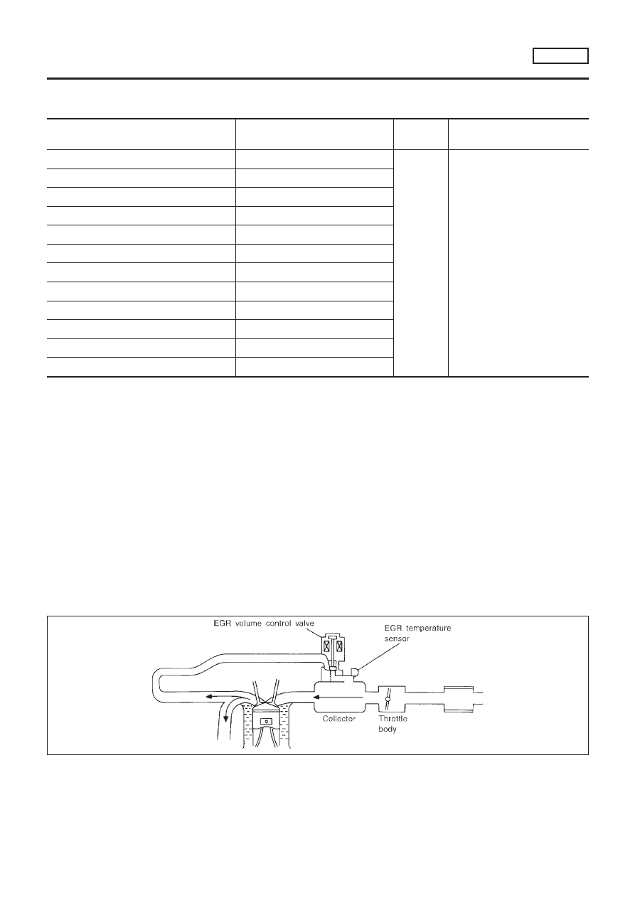
This system controls flow rate of EGR led from exhaust manifold
to intake manifold. The opening of the EGR by-pass passage in the
EGR volume control valve changes to control the flow rate. A
built-in step motor moves the valve in steps corresponding to the
ECM output pulses. The opening of the valve varies for optimum
engine control. The optimum value stored in the ECM is determined
by considering various engine conditions. The EGR volume control
valve remains close under the following conditions.

+

Low engine coolant temperature

+

Engine starting

+

High-speed engine operation

+

Extremely light load engine operation

+

Engine idling

+

Excessively high engine coolant temperature

+

Wide open throttle

+

Mass air flow sensor malfunction

+

Low battery voltage

SEF551W

DTC P0403 EGR VOLUME CONTROL VALVE (CIRCUIT)

(WHERE FITTED)

SR20DE

Description

EC-841

SEF552W

COMPONENT DESCRIPTION

NLEC1553S02

EGR Volume Control Valve

NLEC1553S0201

The EGR volume control valve uses a step motor to control the flow
rate of EGR from exhaust manifold. This motor has four winding
phases. It operates according to the output pulse signal of the
ECM. Two windings are turned ON and OFF in sequence. Each
time an ON pulse is issued, the valve opens or closes, changing
the flow rate. When no change in the flow rate is needed, the ECM
does not issue the pulse signal. A certain voltage signal is issued
so that the valve remains at that particular opening.

CONSULT-II Reference Value in Data Monitor
Mode

NLEC1554

Specification data are reference values.

MONITOR ITEM

CONDITION

SPECIFICATION

EGR VOL CON/V

+

Engine: After warming up

+

Shift lever: “N”

+

No-load

Idle

0 step

Revving engine up to 3,000 rpm
quickly

10 - 55 step

ECM Terminals and Reference Value

NLEC1555

Specification data are reference values and are measured between each terminal and ground.

CAUTION:

Do not use ECM ground terminals when measuring input/output voltage. Doing so may result in dam-
age to the ECM’s transistor. Use a ground other than ECM terminals, such as the ground.

TERMI-

NAL NO.

WIRE

COLOR

ITEM

CONDITION

DATA (DC Voltage)

8
9

17
18

SB
W/B
R/W
G/R

EGR volume control valve

[Engine is running]

+

Warm-up condition

+

Idle speed

0 - 14V

On Board Diagnosis Logic

NLEC1556

DTC No.

Malfunction is detected when ...

Check Items (Possible Cause)

P0403
0403

+

An improper voltage signal is sent to ECM through the
valve.

+

Harness or connectors
(The EGR volume control valve circuit is open or
shorted.)

+

EGR volume control valve

SEF058Y

DTC Confirmation Procedure

NLEC1557

NOTE:
If “DTC Confirmation Procedure” has been previously conducted,
always turn ignition switch “OFF” and wait at least 10 seconds
before conducting the next test.

With CONSULT-II

1)

Turn ignition switch “ON”.

2)

Select “DATA MONITOR” mode with CONSULT-II.

3)

Start engine and warm it up to normal operating temperature.

4)

Rev engine from idle to 2,000 rpm 20 times.

DTC P0403 EGR VOLUME CONTROL VALVE (CIRCUIT)

(WHERE FITTED)

SR20DE

Description (Cont’d)

EC-842

If

1st

trip

DTC

is

detected,

go

to

“DIAGNOSTIC

PROCEDURE”, EC-845.

With GST

Follow the procedure “With CONSULT-II” above.

No Tools

1)

Start engine and warm it up to normal operating temperature.

2)

Rev engine from idle to 2,000 rpm 20 times.

3)

Turn ignition switch “OFF”, wait at least 10 seconds and then
turn “ON”.

4)

Perform “Diagnostic Test Mode II (Self-diagnostic results)” with
ECM.

5)

If DTC is detected, go to “Diagnostic Procedure”, EC-845.

DTC P0403 EGR VOLUME CONTROL VALVE (CIRCUIT)

(WHERE FITTED)

SR20DE

DTC Confirmation Procedure (Cont’d)

EC-843

Wiring Diagram

NLEC1558

YEC701

DTC P0403 EGR VOLUME CONTROL VALVE (CIRCUIT)

(WHERE FITTED)

SR20DE

Wiring Diagram

EC-844

Diagnostic Procedure

NLEC1559

1

CHECK POWER SUPPLY

1. Disconnect EGR volume control valve harness connector.

SEF216X

2. Turn ignition switch “ON”.
3. Check voltage between terminals 2, 5 and ground with CONSULT-II or tester.

SEF782Z

OK or NG

OK

©

GO TO 3.

NG

©

GO TO 2.

2

DETECT MALFUNCTIONING PART

Check the following.

+

15A fuse

+

Harness connectors E76, F36

+

ECM relay

+

Harness for open or short between EGR volume control valve and fuse

©

Repair harness or connectors.

3

CHECK OUTPUT SIGNAL CIRCUIT

1. Turn ignition switch “OFF”.
2. Disconnect ECM harness connector.
3. Check harness continuity between

ECM terminal 8 and EGR volume control valve terminal 1,
ECM terminal 9 and EGR volume control valve terminal 4,
ECM terminal 17 and EGR volume control valve terminal 3,
ECM terminal 18 and EGR volume control valve terminal 6.
Refer to wiring diagram.
Continuity should exist.

4. Also check harness for short to ground and short to power.

OK or NG

OK

©

GO TO 4.

NG

©

Repair open circuit, short to ground or short to power in harness connectors.

DTC P0403 EGR VOLUME CONTROL VALVE (CIRCUIT)

(WHERE FITTED)

SR20DE

Diagnostic Procedure

EC-845

4

CHECK EGR VOLUME CONTROL VALVE

Refer to “COMPONENT INSPECTION”, EC-847.

OK or NG

OK

©

GO TO 5.

NG

©

Replace EGR volume control valve.

5

CHECK INTERMITTENT INCIDENT

Perform “TROUBLE DIAGNOSIS FOR INTERMITTENT INCIDENT”, EC-670.

©

INSPECTION END

DTC P0403 EGR VOLUME CONTROL VALVE (CIRCUIT)

(WHERE FITTED)

SR20DE

Diagnostic Procedure (Cont’d)

EC-846

SEF216X

SEF783Z

SEF015Y

SEF560W

Component Inspection

NLEC1560

EGR VOLUME CONTROL VALVE

NLEC1560S01

With CONSULT-II

1)

Disconnect EGR volume control valve harness connector.

2)

Check resistance between the following terminals.
terminal 2 and terminals 1, 3
terminal 5 and terminals 4, 6

Temperature °C (°F)

Resistance

20 (68)

20.9 - 23.1

3)

Reconnect EGR volume control valve harness connector.

4)

Remove EGR volume control valve from cylinder head.
(The EGR volume control valve harness connector should
remain connected.)

5)

Turn ignition switch “ON”.

6)

Perform “EGR VOL CONT/V” in “ACTIVE TEST” mode with
CONSULT-II. Check that EGR volume control valve shaft
moves smoothly forward and backward according to the valve
opening.
If NG, replace the EGR volume control valve.

Without CONSULT-II

1)

Disconnect EGR volume control valve harness connector.

2)

Check resistance between the following terminals.
terminal 2 and terminals 1, 3
terminal 5 and terminals 4, 6

Temperature °C (°F)

Resistance

20 (68)

20.9 - 23.1

3)

Reconnect EGR volume control valve harness connector.

4)

Remove EGR volume control valve from cylinder head.
(The EGR volume control valve harness connector should
remain connected.)

5)

Turn ignition switch “ON” and “OFF”. Check that EGR volume
control valve shaft moves smoothly forward and backward
according to the ignition switch position.
If NG, replace the EGR volume control valve.

DTC P0403 EGR VOLUME CONTROL VALVE (CIRCUIT)

(WHERE FITTED)

SR20DE

Diagnostic Procedure (Cont’d)

EC-847

SEF184UD

On Board Diagnosis Logic

NLEC1561

The ECM monitors the switching frequency ratio of heated oxygen
sensors 1 (front) and 2 (rear).
A three way catalyst with high oxygen storage capacity will indicate
a low switching frequency of heated oxygen sensor 2 (rear). As
oxygen storage capacity decreases, the heated oxygen sensor 2
(rear) switching frequency will increase.
When the frequency ratio of heated oxygen sensors 1 (front) and
2 (rear) approaches a specified limit value, the three way catalyst
malfunction is diagnosed.

DTC No.

Malfunction is detected when ...

Check Items (Possible Cause)

P0420

+

Three way catalyst does not operate properly.

+

Three way catalyst does not have enough oxygen stor-
age capacity.

+

Three way catalyst

+

Exhaust tube

+

Intake air leaks

+

Injectors

+

Injector leaks

+

Spark plug

+

Improper ignition timing

SEF847Y

SEF848Y

SEF560X

DTC Confirmation Procedure

NLEC1562

CAUTION:

Always drive vehicle at a safe speed.
NOTE:
If “DTC Confirmation Procedure” has been previously conducted,
always turn ignition switch “OFF” and wait at least 10 seconds
before conducting the next test.

With CONSULT-II

TESTING CONDITION:

+

Open engine hood before conducting following proce-
dure.

+

Do not hold engine speed more than specified minutes
below.

1)

Turn ignition switch “ON”.

2)

Select “DTC & SRT CONFIRMATION” then “SRT WORK SUP-
PORT” mode with CONSULT-II.

3)

Start engine.

4)

Rev engine up to 3,000

±

500 rpm and hold it for 3 consecutive

minutes then release the accelerator pedal completely.
If “COMPLETED” appears on the CONSULT-II screen, go to
step 7.

5)

Wait 5 seconds at idle.

6)

Rev engine up to 2,500

±

500 rpm and maintain it until “INCMP”

of CATALYST changes to “CMPLT” (it will take approximately
5 minutes.)
If not “CMPLT”, stop engine and cool it down to less than 70°C
(158°F) and then retest from step 1.

7)

Select “SELF-DIAG RESULTS” mode with CONSULT-II.

8)

Confirm that the 1st trip DTC is not detected.
If the 1st trip DTC is detected, go to “Diagnostic Procedure”,
EC-849.

DTC P0420 THREE WAY CATALYST FUNCTION

SR20DE

On Board Diagnosis Logic

EC-848

SEF074X

Overall Function Check

NLEC1563

Use this procedure to check the overall function of the three way
catalyst. During this check, a 1st trip DTC might not be confirmed.

Without CONSULT-II

1)

Start engine and drive vehicle at a speed of more than 70 km/h
(43 MPH) for 2 consecutive minutes.

2)

Stop vehicle with engine running.

3)

Set voltmeters probes between ECM terminals 62 (HO2S1
signal), 63 (HO2S2 signal) and engine ground.

4)

Keep engine speed at 2,000 rpm constant under no load.

5)

Make sure that the voltage switching frequency (high & low)
between ECM terminal 63 and engine ground is much less
than that of ECM terminal 62 and engine ground.
Switching frequency ratio = A/B
A: Heated oxygen sensor 2 (rear) voltage switching fre-
quency
B: Heated oxygen sensor 1 (front) voltage switching fre-
quency
This ratio should be less than 0.75.
If the ratio is greater than above, it means three way catalyst
does not operate properly.

NOTE:
If the voltage at terminal 62 does not switch periodically more
than 5 times within 10 seconds at step 4, perform trouble
diagnosis for DTC P0133 first. (See EC-729.)

Diagnostic Procedure

NLEC1564

1

CHECK EXHAUST SYSTEM

Visually check exhaust tubes and muffler for dent.

OK or NG

OK

©

GO TO 2.

NG

©

Repair or replace.

DTC P0420 THREE WAY CATALYST FUNCTION

SR20DE

Overall Function Check

EC-849

2

CHECK EXHAUST AIR LEAK

1. Start engine and run it at idle.
2. Listen for an exhaust air leak before the three way catalyst.

SEF099P

OK or NG

OK

©

GO TO 3.

NG

©

Repair or replace.

3

CHECK INTAKE AIR LEAK

Listen for an intake air leak after the mass air flow sensor.

OK or NG

OK

©

GO TO 4.

NG

©

Repair or replace.

4

CHECK IGNITION TIMING

Check for ignition timing.
Refer to “BASIC INSPECTION”, EC-623.

OK or NG

OK

©

GO TO 5.

NG

©

Adjust ignition timing.

5

CHECK INJECTORS

1. Refer to Wiring Diagram for Injectors, EC-1022.
2. Stop engine and then turn ignition switch “ON”.
3. Check voltage between ECM terminals 101, 103, 105 and 107 and ground with CONSULT-II or tester.

SEF075X

Battery voltage should exist.

OK or NG

OK

©

GO TO 6.

NG

©

Perform “Diagnostic Procedure” INJECTOR, EC-1024.

DTC P0420 THREE WAY CATALYST FUNCTION

SR20DE

Diagnostic Procedure (Cont’d)

EC-850

6

CHECK IGNITION SPARK

1. Turn Ignition switch “OFF”.
2. Disconnect ignition wire from spark plug.
3. Connect a known good spark plug to the ignition wire.
4. Place end of spark plug against a suitable ground and crank engine.
5. Check for spark.

SEF282G

OK or NG

OK

©

GO TO 8.

NG

©

GO TO 7.

7

CHECK IGNITION WIRES

Refer to “Component Inspection”, EC-814.

OK or NG

OK

©

Check distributor rotor head for incorrect parts. Check ignition coil, power transistor and
their circuits. Refer to EC-1004.

NG

©

Replace.

8

CHECK INJECTOR

1. Turn ignition switch “OFF”.
2. Remove injector assembly. Refer to EC-578.

Keep fuel hose and all injectors connected to injector gallery.

3. Disconnect camshaft position sensor harness connector.
4. Turn ignition switch “ON”.

Make sure fuel does not drip from injector.

OK or NG

OK (Does not drip)

©

GO TO 9.

NG (Drips)

©

Replace the injector(s) from which fuel is dripping.

9

CHECK INTERMITTENT INCIDENT

Perform “TROUBLE DIAGNOSIS FOR INTERMITTENT INCIDENT”, EC-670.

Trouble is fixed

©

INSPECTION END

Trouble is not fixed

©

Replace three way catalyst.

DTC P0420 THREE WAY CATALYST FUNCTION

SR20DE

Diagnostic Procedure (Cont’d)

EC-851

Description

NLEC1565

SYSTEM DESCRIPTION

NLEC1565S01

Sensor

Input Signal to ECM

ECM func-

tion

Actuator

Camshaft position sensor

Engine speed

EVAP can-
ister purge
control

EVAP canister purge volume
control solenoid valve

Mass air flow sensor

Amount of intake air

Engine coolant temperature sensor

Engine coolant temperature

Battery

Battery voltage

Ignition switch

Start signal

Throttle position switch

Closed throttle position

Throttle position sensor

Throttle position

Heated oxygen sensor 1 (front)

Density of oxygen in exhaust gas
(Mixture ratio feedback signal)

Vehicle speed sensor

Vehicle speed

This system controls flow rate of fuel vapor from the EVAP canis-
ter. The opening of the vapor by-pass passage in the EVAP canis-
ter purge volume control solenoid valve changes to control the flow
rate. The EVAP canister purge volume control solenoid valve
repeats ON/OFF operation according to the signal sent from the
ECM. The opening of the valve varies for optimum engine control.
The optimum value stored in the ECM is determined by consider-
ing various engine conditions. When the engine is operating, the
flow rate of fuel vapor from the EVAP canister is regulated as the
air flow changes.

SEF337U

COMPONENT DESCRIPTION

NLEC1565S02

The EVAP canister purge volume control solenoid valve uses a
ON/OFF duty to control the flow rate of fuel vapor from the EVAP
canister. The EVAP canister purge volume control solenoid valve
is moved by ON/OFF pulses from the ECM. The longer the ON
pulse, the greater the amount of fuel vapor that will flow through the
valve.

CONSULT-II Reference Value in Data Monitor
Mode

NLEC1566

MONITOR ITEM

CONDITION

SPECIFICATION

PURG VOL C/V

+

Engine: After warming up

+

No-load

Idle

0%

Revving engine

DTC P0443 EVAP CANISTER PURGE VOLUME CONTROL SOLENOID VALVE

(CIRCUIT)

SR20DE

Description

EC-852

ECM Terminals and Reference Value

=NLEC1567

Specification data are reference values and are measured between each terminal and ground.

CAUTION:

Do not use ECM ground terminals when measuring input/output voltage. Doing so may result in dam-
age to the ECM’s transistor. Use a ground other than ECM terminals, such as the ground.

TER-

MINAL

NO.

WIRE

COLOR

ITEM

CONDITION

DATA (DC Voltage)

14

P

EVAP canister purge vol-
ume control solenoid valve

[Engine is running]

+

Warm-up condition

+

Idle speed

BATTERY VOLTAGE
(11 - 14V)

[Engine is running]

+

Warm-up condition

+

2,000 rpm

5 - 12V

SEF975W

On Board Diagnosis Logic

NLEC1568

DTC No.

Malfunction is detected when ...

Check Items (Possible Cause)

P0443

+

An improper voltage signal is sent to ECM through the
valve.

+

Harness or connectors
(The valve circuit is open or shorted.)

+

EVAP canister purge volume control solenoid
valve

DTC Confirmation Procedure

NLEC1569

NOTE:
If “DTC Confirmation Procedure” has been previously conducted,
always turn ignition switch “OFF” and wait at least 10 seconds
before conducting the next test.
TESTING CONDITION:
Before performing the following procedure, confirm battery
voltage is more than 11V.

SEF058Y

With CONSULT-II

1)

Turn ignition switch “ON”.

2)

Select “DATA MONITOR” mode with CONSULT-II.

3)

Start engine and let it idle for at least 13 seconds.

4)

If

1st

trip

DTC

is

detected,

go

to

“DIAGNOSTIC

PROCEDURE”, EC-856.

With GST

Follow the procedure “With CONSULT-II” above.

DTC P0443 EVAP CANISTER PURGE VOLUME CONTROL SOLENOID VALVE

(CIRCUIT)

SR20DE

ECM Terminals and Reference Value

EC-853

Wiring Diagram

NLEC1570

MODELS WITH ECM IN ENGINE COMPARTMENT

NLEC1570S01

YEC702

DTC P0443 EVAP CANISTER PURGE VOLUME CONTROL SOLENOID VALVE

(CIRCUIT)

SR20DE

Wiring Diagram

EC-854

MODELS WITH ECM IN CABIN

NLEC1570S02

YEC923

DTC P0443 EVAP CANISTER PURGE VOLUME CONTROL SOLENOID VALVE

(CIRCUIT)

SR20DE

Wiring Diagram (Cont’d)

EC-855

Diagnostic Procedure

NLEC1571

1

CHECK POWER SUPPLY

1. Turn ignition switch “OFF”.
2. Disconnect EVAP canister purge volume control solenoid valve harness connector.

SEF219X

3. Turn ignition switch “ON”.
4. Check voltage between EVAP canister purge volume control solenoid valve terminal 2 and engine ground with CON-

SULT-II or tester.

SEF333X

OK or NG

OK

©

GO TO 3.

NG

©

GO TO 2.

2

DETECT MALFUNCTIONING PART

Check the following.

+

Harness connectors E75, F35 (where fitted)

+

Harness connectors M72, F44 (where fitted)

+

Harness connectors F13, F60

+

10A fuse

+

Harness for open or short between EVAP canister purge volume control solenoid valve and fuse

©

Repair harness or connectors.

3

CHECK OUTPUT SIGNAL CIRCUIT

1. Turn ignition switch “OFF”.
2. Disconnect ECM harness connector.
3. Check harness continuity between ECM terminal 14 and EVAP canister purge volume control solenoid valve terminal 1.

Refer to wiring diagram.

Continuity should exist.

4. Also check harness for short to ground and short to power.

OK or NG

OK

©

GO TO 5.

NG

©

GO TO 4.

DTC P0443 EVAP CANISTER PURGE VOLUME CONTROL SOLENOID VALVE

(CIRCUIT)

SR20DE

Diagnostic Procedure

EC-856


Content      ..     78      79      80      81     ..