Nissan Almera Tino V10 (2001 year). Manual - part 72
MODELS WITH ECM IN CABIN
NLEC1419S04
YEC916
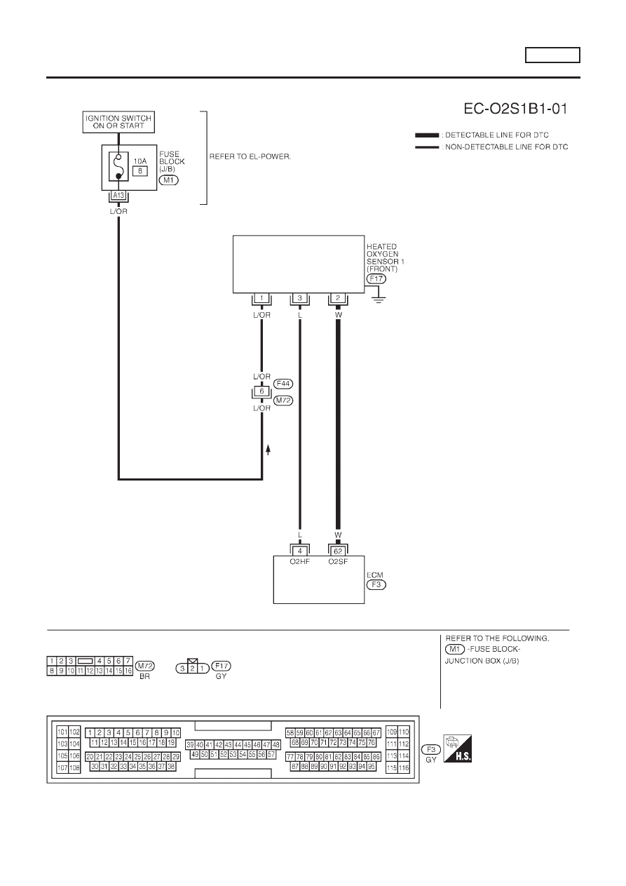
DTC P0130 HEATED OXYGEN SENSOR 1 (FRONT) (CIRCUIT)
SR20DE
Wiring Diagram (Cont’d)
EC-713
|
|
|
MODELS WITH ECM IN CABIN NLEC1419S04 YEC916 DTC P0130 HEATED OXYGEN SENSOR 1 (FRONT) (CIRCUIT) SR20DE Wiring Diagram (Cont’d) EC-713 |