Nissan Almera Tino V10 (2001 year). Manual - part 66
SEF139P
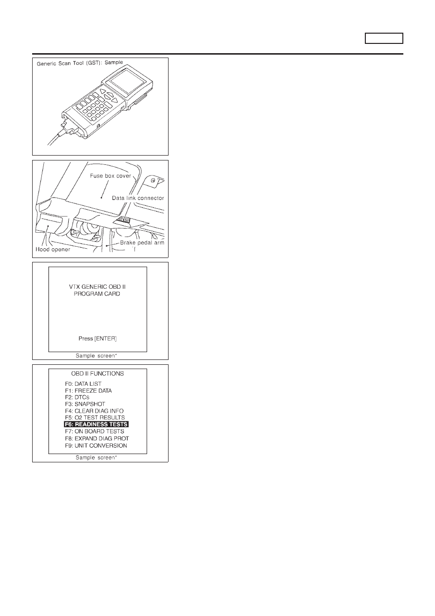
Generic Scan Tool (GST)
=NLEC1366
DESCRIPTION
NLEC1366S01
Generic Scan Tool (OBDII scan tool) complying with ISO 15031-4
has 9 different functions explained on the next page.
ISO 9141 is used as the protocol.
The name “GST” or “Generic Scan Tool” is used in this service
manual.
SEF094Y
GST INSPECTION PROCEDURE
NLEC1366S02
1.
Turn ignition switch OFF.
2.
Connect “GST” to data link connector which is located under
lower dash panel near the fuse box cover.
SEF398S
3.
Turn ignition switch ON.
4.
Enter the program according to instruction on the screen or in
the operation manual.
(*: Regarding GST screens in this section, sample screens are
shown.)
SEF416S
5.
Perform each diagnostic mode according to each service pro-
cedure.
For further information, see the GST Operation Manual of the
tool maker.
ON BOARD DIAGNOSTIC SYSTEM DESCRIPTION
SR20DE
Generic Scan Tool (GST)
EC-617