Nissan Almera Tino V10 (2001 year). Manual - part 64


  Index      Manuals     Nissan Almera Tino V10 (2001 year) - Service and Repair Manual


Search            copyright infringement  


Content      ..     62      63      64      65     ..


Nissan Almera Tino V10 (2001 year). Manual - part 64


CONSULT-II or GST (Generic Scan Tool) Examples: P0340, P1320, P0705, P0750, etc.
These DTCs are prescribed by ISO 15031-6.
(CONSULT-II also displays the malfunctioning component or system.)

+

1st trip DTC No. is the same as DTC No.

+

Output of a DTC indicates a malfunction. However, Mode II and GST do not indicate whether the
malfunction is still occurring or has occurred in the past and has returned to normal.
CONSULT-II can identify malfunction status as shown below. Therefore, using CONSULT-II (if avail-
able) is recommended.

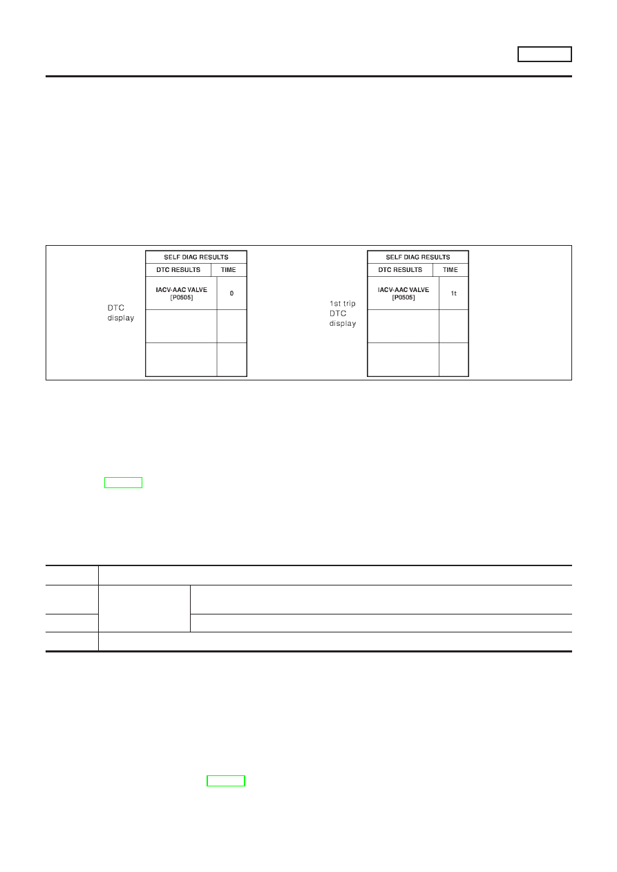
A sample of CONSULT-II display for DTC is shown below. DTC or 1st trip DTC of a malfunction is displayed
in SELF-DIAGNOSTIC RESULTS mode of CONSULT-II. Time data indicates how many times the vehicle was
driven after the last detection of a DTC.
If the DTC is being detected currently, the time data will be “0”.
If a 1st trip DTC is stored in the ECM, the time data will be “[1t]”.

SEF698X

Freeze Frame Data and 1st Trip Freeze Frame Data

NLEC1361S0102

The ECM records the driving conditions such as fuel system status, calculated load value, engine coolant
temperature, short term fuel trim, long term fuel trim, engine speed, vehicle speed, absolute throttle position,
base fuel schedule and intake air temperature at the moment a malfunction is detected.
Data which are stored in the ECM memory, along with the 1st trip DTC, are called 1st trip freeze frame data.
The data, stored together with the DTC data, are called freeze frame data and displayed on CONSULT-II or
GST. The 1st trip freeze frame data can only be displayed on the CONSULT-II screen, not on the GST. For
details, see EC-610.
Only one set of freeze frame data (either 1st trip freeze frame data or freeze frame data) can be stored in the
ECM. 1st trip freeze frame data is stored in the ECM memory along with the 1st trip DTC. There is no prior-
ity for 1st trip freeze frame data and it is updated each time a different 1st trip DTC is detected. However, once
freeze frame data (2nd trip detection/MI on) is stored in the ECM memory, 1st trip freeze frame data is no
longer stored. Remember, only one set of freeze frame data can be stored in the ECM. The ECM has the fol-
lowing priorities to update the data.

Priority

Items

1

Freeze frame data

Misfire — DTC: P0300 - P0304 (0300 - 0304)
Fuel Injection System Function — DTC: P0171 (0171), P0172 (0172)

2

Except the above items (Includes CVT related items)

3

1st trip freeze frame data

For example, the EGR malfunction (Priority: 2) was detected and the freeze frame data was stored in the 2nd
trip. After that when the misfire (Priority: 1) is detected in another trip, the freeze frame data will be updated
from the EGR malfunction to the misfire. The 1st trip freeze frame data is updated each time a different mal-
function is detected. There is no priority for 1st trip freeze frame data. However, once freeze frame data is
stored in the ECM memory, 1st trip freeze data is no longer stored (because only one freeze frame data or
1st trip freeze frame data can be stored in the ECM). If freeze frame data is stored in the ECM memory and
freeze frame data with the same priority occurs later, the first (original) freeze frame data remains unchanged
in the ECM memory.
Both 1st trip freeze frame data and freeze frame data (along with the DTCs) are cleared when the ECM
memory is erased. Procedures for clearing the ECM memory are described in “How to Erase Emission-related
Diagnostic Information”. Refer to EC-594.

ON BOARD DIAGNOSTIC SYSTEM DESCRIPTION

SR20DE

Emission-related Diagnostic Information (Cont’d)

EC-585

System Readiness Test (SRT) Code

NLEC1361S0103

System Readiness Test (SRT) code is specified in Mode 1 of ISO 15031-5.
As part of an emissions test for Inspection & Maintenance (I/M), certain states require the status of SRT be
used to indicate whether the ECM has completed self-diagnosis of major emission systems and components.
Completion must be verified in order for the emissions inspection to proceed.
If a vehicle is rejected for a State emissions inspection due to one or more SRT items indicating “INCMP”,
use the information in this Service Manual to set the SRT to “CMPLT”.
In most cases the ECM will automatically complete its self-diagnosis cycle during normal usage, and the SRT
status will indicate “CMPLT” for each application system. Once set as “CMPLT”, the SRT status remains
“CMPLT” until the self-diagnosis memory is erased.
Occasionally, certain portions of the self-diagnostic test may not be completed as a result of the customer’s
normal driving pattern; the SRT will indicate “INCMP” for these items.
NOTE:
The SRT will also indicate “INCMP” if the self-diagnosis memory is erased for any reason or if the ECM
memory power supply is interrupted for several hours.
If, during the state emissions inspection, the SRT indicates “CMPLT” for all test items, the inspector will con-
tinue with the emissions test. However, if the SRT indicates “INCMP” for one or more of the SRT items the
vehicle is returned to the customer untested.
NOTE:
If MI is “ON” during the state emissions inspection, the vehicle is also returned to the customer untested even
though the SRT indicates “CMPLT” for all test items. Therefore, it is important to check SRT (“CMPLT”) and
DTC (No DTCs) before the inspection.

SRT Item

NLEC1361S0104

The table below shows required self-diagnostic items to set the SRT to “CMPLT”.

SRT item

(CONSULT-II indica-

tion)

Perfor-

mance Pri-

ority*1

Required self-diagnostic items to set the SRT to “CMPLT”

Corresponding

DTC No.

CATALYST

3

Three way catalyst function

P0420

O2 SENSOR

3

Heated oxygen sensor 1 (front) (circuit)

P0130

Heated oxygen sensor 1 (front) (lean shift monitoring)

P0131

Heated oxygen sensor 1 (front) (rich shift monitoring)

P0132

Heated oxygen sensor 1 (front) (response monitoring)

P0133

Heated oxygen sensor 1 (front) (high voltage)

P0134

Heated oxygen sensor 2 (rear) (min. voltage monitoring)

P0137

Heated oxygen sensor 2 (rear) (max. voltage monitoring)

P0138

Heated oxygen sensor 2 (rear) (response monitoring)

P0139

Heated oxygen sensor 2 (rear) (high voltage)

P0140

O2 SEN HEATER

3

Front heated oxygen sensor 1 heater (front)

P0135

Rear heated oxygen sensor 1 heater (rear)

P0141

EGR SYSTEM

3

EGR function (close)

P0400

1

EGR function (open)

P1402

*1: If completion of several SRTs is required, perform driving patterns (DTC confirmation procedure), one by one based on the priority
for models with CONSULT-II.

ON BOARD DIAGNOSTIC SYSTEM DESCRIPTION

SR20DE

Emission-related Diagnostic Information (Cont’d)

EC-586

SRT Set Timing

=NLEC1361S0105

SRT is set as “CMPLT” after self-diagnosis has been performed one or more times. Completion of SRT is done
regardless of whether the result is OK or NG. The set timing is different between OK and NG results and is
shown in the table below.

Self-diagnosis result

Example

Diagnosis

Ignition cycle

ON

OFF

ON

OFF

ON

OFF

ON

All OK

Case 1

P0400

OK (1)

— (1)

OK (2)

— (2)

P0402

OK (1)

— (1)

— (1)

OK (2)

P1402

OK (1)

OK (2)

— (2)

— (2)

SRT of EGR

“CMPLT”

“CMPLT”

“CMPLT”

“CMPLT”

Case 2

P0400

OK (1)

— (1)

— (1)

— (1)

P0402

— (0)

— (0)

OK (1)

— (1)

P1402

OK (1)

OK (2)

— (2)

— (2)

SRT of EGR

“INCMP”

“INCMP”

“CMPLT”

“CMPLT”

NG exists

Case 3

P0400

OK

OK

P0402

P1402

NG

NG

NG

(Consecutive

NG)

(1st trip)

DTC

1st trip DTC

1st trip DTC

DTC

(= MIL “ON”)

SRT of EGR

“INCMP”

“INCMP”

“INCMP”

“CMPLT”

OK: Self-diagnosis is carried out and the result is OK.
NG: Self-diagnosis is carried out and the result is NG.
—: Self-diagnosis is not carried out.

When all SRT related self-diagnoses showed OK results in a single cycle (Ignition OFF-ON-OFF), the SRT
will indicate “CMPLT”.

Case 1 above

When all SRT related self-diagnoses showed OK results through several different cycles, the SRT will indi-
cate “CMPLT” at the time the respective self-diagnoses have at least one OK result.

Case 2 above

If one or more SRT related self-diagnoses showed NG results in 2 consecutive cycles, the SRT will also indi-
cate “CMPLT”.

Case 3 above

The table above shows that the minimum number of cycles for setting SRT as “INCMP” is one (1) for each
self-diagnosis (Case 1 & 2) or two (2) for one of self-diagnoses (Case 3). However, in preparation for the state
emissions inspection, it is unnecessary of each self-diagnosis to be executed twice (Case 3) for the following
reasons:

+

The SRT will indicate “CMPLT” at the time the respective self-diagnoses have one (1) OK result.

+

The emissions inspection requires “CMPLT” of the SRT only with OK self-diagnosis results.

+

When, during SRT driving pattern, 1st trip DTC (NG) is detected prior to “CMPLT” of SRT, the self-diag-
nosis memory must be erased from ECM after repair.

+

If the 1st trip DTC is erased, all the SRT will indicate “INCMP”.

NOTE:
SRT can be set as “CMPLT” together with the DTC(s). Therefore, DTC check must always be carried out prior
to the state emission inspection even though the SRT indicates “CMPLT”.

SRT Service Procedure

NLEC1361S0106

If a vehicle has failed the state emissions inspection due to one or more SRT items indicating “INCMP”, review
the flowchart diagnostic sequence on the next page.

ON BOARD DIAGNOSTIC SYSTEM DESCRIPTION

SR20DE

Emission-related Diagnostic Information (Cont’d)

EC-587

SEF573XC

*1

EC-584

*2

EC-588

*3

EC-589

How to Display SRT Code

NLEC1361S0107

1.

With CONSULT-II

Selecting “SRT STATUS” in “DTC CONFIRMATION” mode with CONSULT-II.
For items whose SRT codes are set, a “CMPLT” is displayed on the CONSULT-II screen; for items whose
SRT codes are not set, “INCMP” is displayed as shown below.

ON BOARD DIAGNOSTIC SYSTEM DESCRIPTION

SR20DE

Emission-related Diagnostic Information (Cont’d)

EC-588

SEF821Y

2.

With GST

Selecting Mode 1 with GST (Generic Scan Tool)

How to Set SRT Code

NLEC1361S0108

To set all SRT codes, self-diagnosis for the items indicated above must be performed one or more times. Each
diagnosis may require a long period of actual driving under various conditions.

With CONSULT-II

Perform corresponding DTC Confirmation Procedure one by one based on “Performance Priority” in the table
on EC-646.

Without CONSULT-II

The most efficient driving pattern in which SRT codes can be properly set is explained on the next page. The
driving pattern should be performed one or more times to set all SRT codes.

ON BOARD DIAGNOSTIC SYSTEM DESCRIPTION

SR20DE

Emission-related Diagnostic Information (Cont’d)

EC-589

Driving

Pattern

=NLEC1361S0109

NEF321A

ON

BOARD

DIAGNOSTIC

SYSTEM

DESCRIPTION

SR20DE

Emission-related

Diagnostic

Information

(Cont’d)

EC-590

+

The time required for each diagnosis varies with road surface conditions, weather, altitude, individual driv-
ing habits, etc.
Zone A refers to the range where the time required, for the diagnosis under normal conditions*, is the
shortest. Zone B refers to the range where the diagnosis can still be performed if the diagnosis is not
completed within zone A.

*: Normal conditions refer to the following:

Sea level

Flat road

Ambient air temperature: 20 - 30°C (68 - 86°F)

Diagnosis is performed as quickly as possible under normal conditions.
Under different conditions [For example: ambient air temperature other than 20 - 30°C (68 - 86°F)], diag-
nosis may also be performed.

Pattern 1:

+

The engine is started at the engine coolant temperature of −10 to 35°C (14 to 95°F) (where the volt-
age between the ECM terminal 70 and ground is 3.0 - 4.3V).

+

The engine must be operated at idle speed until the engine coolant temperature is greater than 70°C
(158°F) (where the voltage between the ECM terminal 70 and ground is lower than 1.4V).

Pattern 2:

+

When steady-state driving is performed again even after it is interrupted, each diagnosis can be conducted.
In this case, the time required for diagnosis may be extended.

*1: Depress the accelerator pedal until vehicle speed is 90 km/h (56 MPH), then release the accelerator pedal
and keep it released for more than 10 seconds. Depress the accelerator pedal until vehicle speed is 90 km/h
(56 MPH) again.
*2: Checking the vehicle speed with GST is advised.
Suggested transmission gear position for CVT models
Set the selector lever in the “D” position with “SPORTS MODE SW” ON.

Test Value and Test Limit (GST only — not applicable to CONSULT-II)

NLEC1361S0110

The following is the information specified in Mode 6 of ISO 15031-5.
The test value is a parameter used to determine whether a system/circuit diagnostic test is “OK” or “NG” while
being monitored by the ECM during self-diagnosis. The test limit is a reference value which is specified as the
maximum or minimum value and is compared with the test value being monitored.
Items for which these data (test value and test limit) are displayed are the same as SRT code items (14 test
items).
These data (test value and test limit) are specified by Test ID (TID) and Component ID (CID) and can be dis-
played on the GST screen.

X: Applicable

—: Not applicable

SRT item

Self-diagnostic test item

Test value (GST display)

Test limit

Application

TID

CID

CATALYST

Three way catalyst function

01H

01H

Max.

X

02H

81H

Min.

X

HO2S

Heated oxygen sensor 1

(front)

09H

04H

Max.

X

0AH

84H

Min.

X

0BH

04H

Max.

X

0CH

04H

Max.

X

0DH

04H

Max.

X

Heated oxygen sensor 2

(rear)

19H

86H

Min.

X

1AH

86H

Min.

X

1BH

06H

Max.

X

1CH

06H

Max.

X

ON BOARD DIAGNOSTIC SYSTEM DESCRIPTION

SR20DE

Emission-related Diagnostic Information (Cont’d)

EC-591

SRT item

Self-diagnostic test item

Test value (GST display)

Test limit

Application

TID

CID

HO2S HTR

Heated oxygen sensor 1

heater (front)

29H

08H

Max.

X

2AH

88H

Min.

X

Heated oxygen sensor 2

heater (rear)

2DH

0AH

Max.

X

2EH

8AH

Min.

X

EGR SYSTEM

(where fitted)

EGR function

(where fitted)

31H

8CH

Min.

X

32H

8CH

Min.

X

33H

8CH

Min.

X

34H

8CH

Min.

X

35H

0CH

Max.

X

Emission-related Diagnostic Information Items

NLEC1361S0111

X: Applicable

—: Not applicable

Items

(CONSULT-II screen terms)

DTC*1

SRT code

Test value/Test

limit

(GST only)

1st trip DTC*1

Reference page

NO SELF DIAGNOSTIC FAIL-
URE INDICATED

P0000

MAF SEN/CIRCUIT

P0100

X

EC-679

AIR TEMP SEN/CIRC

P0110

X

EC-687

COOLANT T SEN/CIRC

P0115

X

EC-694

THRTL POS SEN/CIRC

P0120

X

EC-700

HO2S1 (B1)

P0130

X

X

X*2

EC-709

HO2S1 (B1)

P0131

X

X

X*2

EC-717

HO2S1 (B1)

P0132

X

X

X*2

EC-723

HO2S1 (B1)

P0133

X

X

X*2

EC-729

HO2S1 (B1)

P0134

X

X

X*2

EC-739

HO2S1 HTR (B1)

P0135

X

X

X*2

EC-746

HO2S2 (B1)

P0137

X

X

X*2

EC-752

HO2S2 (B1)

P0138

X

X

X*2

EC-761

HO2S2 (B1)

P0139

X

X

X*2

EC-770

HO2S2 (B1)

P0140

X

X

X*2

EC-779

HO2S2 HTR (B1)

P0141

X

X

X*2

EC-786

FUEL SYS-LEAN/BK1

P0171

X

EC-792

FUEL SYS-RICH/BK1

P0172

X

EC-800

MULTI CYL MISFIRE

P0300

X

EC-808

CYL 1 MISFIRE

P0301

X

EC-808

CYL 2 MISFIRE

P0302

X

EC-808

CYL 3 MISFIRE

P0303

X

EC-808

CYL 4 MISFIRE

P0304

X

EC-808

ON BOARD DIAGNOSTIC SYSTEM DESCRIPTION

SR20DE

Emission-related Diagnostic Information (Cont’d)

EC-592

Items

(CONSULT-II screen terms)

DTC*1

SRT code

Test value/Test

limit

(GST only)

1st trip DTC*1

Reference page

KNOCK SEN/CIRC-B1

P0325

EC-815

CKP SEN/CIRCUIT

P0335

X

EC-819

CMP SEN/CIRCUIT

P0340

X

EC-825

EGR SYSTEM (where fitted)

P0400

X

X

X*2

EC-834

EGR VOL CONT/V CIRC
(where fitted)

P0403

X

EC-841

TW CATALYST SYS-B1

P0420

X

X

X*2

EC-848

PURG VOLUME CONT/V

P0443

X

EC-852

VEH SPEED SEN/CIRC

P0500

X

EC-858

IACV/AAC VLV/CIRC

P0505

X

EC-863

CLOSED TP SW/CIRC

P0510

X

EC-872

ECM

P0605

X

EC-880

PNP SW/CIRC

P0705

X

Refer to AT sec-

tion.

ATF TEMP SEN/CIRC

P0710

X

Refer to AT sec-

tion.

IN PY SPD SEN/CIRC

P0715

X

Refer to AT sec-

tion.

VEH SPD SEN/CIR AT

P0720

X

Refer to AT sec-

tion.

ENGINE SPEED SIG

P0725

X

Refer to AT sec-

tion.

TCC SOLENOID/CIRC

P0740

X

Refer to AT sec-

tion.

L/PRESS SOL/CIRC

P0745

X

Refer to AT sec-

tion.

ENG OVER TEMP

P1217

X

EC-882

CKP SENSOR (COG)

P1336

X

EC-909

EGR TEMP SEN/CIRC
(where fitted)

P1401

X

EC-915

EGR SYSTEM (where fitted)

P1402

X

X

X*2

EC-921

A/T DIAG COMM LINE

P1605

X

EC-928

TP SEN/CIRC A/T

P1705

X

Refer to AT sec-

tion.

P-N POS SW/CIRCUIT

P1706

X

EC-931

O/R CLTCH SOL/CIRC

P1760

X

Refer to AT sec-

tion.

STEP MOTR CIRC

P1777

X

Refer to AT sec-

tion.

STEP MOTR FNC

P1778

X

Refer to AT sec-

tion.

ON BOARD DIAGNOSTIC SYSTEM DESCRIPTION

SR20DE

Emission-related Diagnostic Information (Cont’d)

EC-593

Items

(CONSULT-II screen terms)

DTC*1

SRT code

Test value/Test

limit

(GST only)

1st trip DTC*1

Reference page

LINE PRESS SEN

P1791

X

Refer to AT sec-

tion.

*1: 1st trip DTC No. is the same as DTC No.
*2: These are not displayed with GST.

How to Erase Emission-related Diagnostic Information

NLEC1361S0112

How to Erase DTC (With CONSULT-II)

NOTE:
If the DTC is not for CVT related items (see EC-550), 
skip steps 2 through 4.
1) If the ignition switch stays “ON” after repair work, be sure to turn ignition switch “OFF” once. Wait at least

10 seconds and then turn it “ON” (engine stopped) again.

2) Turn CONSULT-II “ON” and touch “CVT”.
3) Touch “SELF-DIAG RESULTS”.
4) Touch “ERASE”. [The DTC in the TCM (Transmission control module) will be erased.] Then touch “BACK”

twice.

5) Touch “ENGINE”.
6) Touch “SELF-DIAG RESULTS”.
7) Touch “ERASE”. (The DTC in the ECM will be erased.)

+

If DTCs are displayed for both ECM and TCM (Transmission control module), they need to be erased
individually from the ECM and TCM (Transmission control module).

SEF905Z

ON BOARD DIAGNOSTIC SYSTEM DESCRIPTION

SR20DE

Emission-related Diagnostic Information (Cont’d)

EC-594

The emission-related diagnostic information can be erased by selecting “ERASE” in the “SELF-DIAG
RESULTS” mode with CONSULT-II.
How to Erase DTC (

With GST)

NOTE:
If the DTC is not for CVT related items (see EC-550), 
skip step 2.
1) If the ignition switch stays “ON” after repair work, be sure to turn ignition switch “OFF” once. Wait at least

10 seconds and then turn it “ON” (engine stopped) again.

2) Perform “SELF-DIAGNOSTIC PROCEDURE (Without CONSULT-II)” in AT section titled “TROUBLE

DIAGNOSIS”, “Self-diagnosis”. (The engine warm-up step can be skipped when performing the diagnosis
only to erase the DTC.)

3) Select Mode 4 with GST (Generic Scan Tool).
The emission-related diagnostic information can be erased by selecting Mode 4 with GST (Generic Scan Tool).
NOTE:

+

If the battery is disconnected, the emission-related diagnostic information will be lost after approx.
24 hours.

+

Erasing the emission-related diagnostic information using CONSULT-II or GST is easier and
quicker than switching the mode using the data link connector.

+

The following data are cleared when the ECM memory is erased.

1) Diagnostic trouble codes
2) 1st trip diagnostic trouble codes
3) Freeze frame data
4) 1st trip freeze frame data
5) System readiness test (SRT) codes
6) Test values
7) Distance traveled while MI is activated
8) Others
Actual work procedures are explained using a DTC as an example. Be careful so that not only the DTC, but
all of the data listed above, are cleared from the ECM memory during work procedures.

MODELS WITHOUT EURO-OBD SYSTEM

NLEC1361S02

DTC and 1st Trip DTC

NLEC1361S0201

The 1st trip DTC (whose number is the same as the DTC number) is displayed for the latest self-diagnostic
result obtained. If the ECM memory was cleared previously, and the 1st trip DTC did not reoccur, the 1st trip
DTC will not be displayed.
If a malfunction is detected during the 1st trip, the 1st trip DTC is stored in the ECM memory. If the same mal-
function is not detected in the 2nd trip (meeting the required driving pattern), the 1st trip DTC is cleared from
the ECM memory. If the same malfunction is detected in the 2nd trip, both the 1st trip DTC and DTC are stored
in the ECM memory. In other words, the DTC is stored in the ECM memory when the same malfunction occurs
in two consecutive trips. If a 1st trip DTC is stored and a non-diagnostic operation is performed between the
1st and 2nd trips, only the 1st trip DTC will continue to be stored. For fail-safe items, the DTC is stored in the
ECM memory even in the 1st trip.
Procedures for clearing the DTC and the 1st trip DTC from the ECM memory are described in “How to Erase
Emission-related Diagnostic Information”, EC-596.
When a (1st trip) DTC is detected, check, print out or write down and erase (1st trip) DTC and Freeze Frame
data as specified in “Work Flow” procedure Step II, refer to EC-621. Then perform “DTC Confirmation Proce-
dure” or “Overall Function Check” to try to duplicate the problem. If the malfunction is duplicated, the item
requires repair.
How to Read DTC and 1st Trip DTC
DTC and 1st trip DTC can be read by the following methods.

Without CONSULT-II

ECM displays the DTC by a set of four digit numbers with MI illumination in the diagnostic test mode II (Self-
diagnostic results). Example: 0100, 0115, 0340, 1335, etc.

With CONSULT-II

CONSULT-II displays the DTC in “SELF-DIAG RESULTS” mode. Examples: P0100, P0115, P0340, P1335,
etc.
(CONSULT-II also displays the malfunctioning component or system.)

+

1st trip DTC No. is the same as DTC No.

ON BOARD DIAGNOSTIC SYSTEM DESCRIPTION

SR20DE

Emission-related Diagnostic Information (Cont’d)

EC-595

+

Output of a DTC indicates a malfunction. However, ECM in the diagnostic test mode II (Self-diag-
nostic results) does not indicate whether the malfunction is still occurring or has occurred in the
past and has returned to normal. CONSULT-II can identify malfunction status as shown below.
Therefore, the use of CONSULT-II (if available) is recommended.

A sample CONSULT-II display for DTC and 1st trip DTC is shown below. DTC or 1st trip DTC of a malfunc-
tion is displayed in the SELF-DIAGNOSTIC RESULTS mode of CONSULT-II. Time data indicates how many
times the vehicle was driven after the last detection of a DTC.
If the DTC is being detected currently, the time data will be “0”.
If a 1st trip DTC is stored in the ECM, the time data will be “[1t]”.

SEF992X

Freeze Frame Data and 1st Trip Freeze Frame Data

NLEC1361S0202

The ECM records the driving conditions such as fuel system status, calculated load value, engine coolant
temperature, short term fuel trim, long term fuel trim, engine speed, vehicle speed, throttle valve opening, base
fuel schedule and intake air temperature at the moment a malfunction is detected.
Data which are stored in the ECM memory, along with the 1st trip DTC, are called 1st trip freeze frame data.
The data, stored together with the DTC data, are called freeze frame data and displayed on CONSULT-II. For
details, see EC-610.
Only one set of freeze frame data (either 1st trip freeze frame data or freeze frame data) can be stored in the
ECM. 1st trip freeze frame data is stored in the ECM memory along with the 1st trip DTC. There is no prior-
ity for 1st trip freeze frame data and it is updated each time a different 1st trip DTC is detected. However, once
freeze frame data is stored in the ECM memory, 1st trip freeze frame data is no longer stored. Remember,
only one set of freeze frame data can be stored in the ECM.
If freeze frame data is stored in the ECM memory and another freeze frame data occurs later, the first (origi-
nal) freeze frame data remains unchanged in the ECM memory.
Both 1st trip freeze frame data and freeze frame data (along with the DTCs) are cleared when the ECM
memory is erased. Procedures for clearing the ECM memory are described in “How to Erase Emission-related
Diagnostic Information”, EC-596.

How to Erase Emission-related Diagnostic Information

NLEC1361S0203

How to Erase DTC (

With CONSULT-II)

1) If the ignition switch stays “ON” after repair work, be sure to turn ignition switch “OFF” once. Wait at least

10 seconds and then turn it “ON” (engine stopped) again.

2) Touch “ENGINE”.
3) Touch “SELF-DIAG RESULTS”.
4) Touch “ERASE”. (The DTC in the ECM will be erased.)

ON BOARD DIAGNOSTIC SYSTEM DESCRIPTION

SR20DE

Emission-related Diagnostic Information (Cont’d)

EC-596

SEF993X

The emission related diagnostic information in the ECM can be erased by selecting “ERASE” in the “SELF-
DIAG RESULTS” mode with CONSULT-II.
How to Erase DTC (

Without CONSULT-II)

1) If the ignition switch stays “ON” after repair work, be sure to turn ignition switch “OFF” once. Wait at least

10 seconds and then turn it “ON” (engine stopped) again.

2) Change the diagnostic test mode from Mode II to Mode I by using the data link connector. (See EC-600.)
The emission related diagnostic information in the ECM can be erased by changing the diagnostic test mode.

+

If the battery is disconnected, the emission-related diagnostic information will be lost after approx.
24 hours.

+

Erasing the emission-related diagnostic information using CONSULT-II is easier and quicker than
switching the diagnostic test mode using the data link connector.

+

The following data are cleared when the ECM memory is erased.

1) Diagnostic trouble codes
2) 1st trip diagnostic trouble codes
3) Freeze frame data
4) 1st trip freeze frame data
5) Others
Actual work procedures are explained using a DTC as an example. Be careful so that not only the DTC, but
all of the data listed above, are cleared from the ECM memory during work procedures.

SEF543X

NATS (Nissan Anti-theft System)

NLEC1362

+

If the security indicator lights up with the ignition switch
in the “ON” position or “NATS MALFUNCTION” is dis-
played on “SELF-DIAG RESULTS” screen, perform self-
diagnostic results mode with CONSULT-II using NATS pro-
gram card. Refer to NATS (Nissan Anti-Theft System) in EL
section.

+

Confirm no self-diagnostic results of NATS is displayed
before touching “ERASE” in “SELF-DIAG RESULTS”
mode with CONSULT-II.

+

When replacing ECM, initialization of NATS system and

ON BOARD DIAGNOSTIC SYSTEM DESCRIPTION

SR20DE

Emission-related Diagnostic Information (Cont’d)

EC-597

registration of all NATS ignition key IDs must be carried
out with CONSULT-II using NATS program card.
Therefore, be sure to receive all keys from vehicle owner.
Regarding the procedure of NATS initialization and NATS
ignition key ID registration, refer to CONSULT-II operation
manual, NATS.

Malfunction Indicator (MI)

DESCRIPTION

NLEC1363

SAT652J

The MI is located on the instrument panel.
1. The MI will light up when the ignition switch is turned ON without the engine running. This is a bulb check.

+

If the MI does not light up, refer to EL-156, “WARNING LAMPS” or see EC-1060.

2. When the engine is started, the MI should go off.

If the MI remains on, the on board diagnostic system has detected an engine system malfunction.

On Board Diagnostic System Function

NLEC1363S01

The on board diagnostic system has the following four functions.
Diagnostic Test Mode I
1. BULB CHECK:

This function checks the MI bulb for damage (blown, open circuit, etc.).
If the MI does not come on, check MI circuit and ECM test mode selector. (See the following page.)

2. MALFUNCTION WARNING:

MI

Condition

ON

When the malfunction is detected or the ECM’s CPU is malfunctioning.

OFF

No malfunction.

Diagnostic Test Mode II
3. SELF-DIAGNOSTIC RESULTS:

This function allows DTCs and 1st trip DTCs to be read.

4. HEATED OXYGEN SENSOR 1 MONITOR (FRONT):

This function allows the fuel mixture condition (lean or rich), monitored by heated oxygen sensor 1 (front),
to be read.

MI Flashing without DTC

NLEC1363S0101

If the ECM is in Diagnostic Test Mode II, MI may flash when engine is running. In this case, check ECM test
mode following “How to Switch Diagnostic Test Modes”.
How to switch the diagnostic test (function) modes, and details of the above functions are described later.
(Refer to EC-600.)

ON BOARD DIAGNOSTIC SYSTEM DESCRIPTION

SR20DE

NATS (Nissan Anti-theft System) (Cont’d)

EC-598

Condition

Diagnostic Test Mode I

Diagnostic Test Mode II

Ignition switch in “ON” position

Engine stopped

BULB CHECK

SELF-DIAGNOSTIC RESULTS

Engine running

MALFUNCTION WARNING

HEATED OXYGEN SENSOR 1

MONITOR (FRONT)

The following emission-related diagnostic information is cleared when the ECM memory is erased.
1) Diagnostic trouble codes
2) 1st trip diagnostic trouble codes
3) Freeze frame data
4) 1st trip freeze frame data
5) System readiness test (SRT) codes
6) Test values
7) Distance traveled while MI is activated
8) Others

ON BOARD DIAGNOSTIC SYSTEM DESCRIPTION

SR20DE

Malfunction Indicator (MI) (Cont’d)

EC-599

How to Switch Diagnostic Test Modes

NLEC1363S02

SEF951WC

*1: EC-1060
*2: EC-598

*3: EC-1060

*4: EC-647

ON BOARD DIAGNOSTIC SYSTEM DESCRIPTION

SR20DE

Malfunction Indicator (MI) (Cont’d)

EC-600


Content      ..     62      63      64      65     ..