Nissan Almera Tino V10 (2001 year). Manual - part 60


  Index      Manuals     Nissan Almera Tino V10 (2001 year) - Service and Repair Manual


Search            copyright infringement  


Content      ..     58      59      60      61     ..


Nissan Almera Tino V10 (2001 year). Manual - part 60


3

DETECT MALFUNCTIONING PART

Check the following.

+

10A fuse

+

15A fuse

+

Harness for open or short between fuse and fuel pump relay

©

Repair harness or connectors.

4

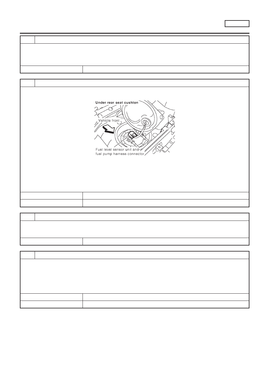
CHECK POWER GROUND CIRCUIT

1. Turn ignition switch “OFF”.
2. Disconnect fuel level sensor unit and fuel pump harness connector.

SEF632Z

3. Check harness continuity between fuel level sensor unit and fuel pump harness connector terminal 3 and body ground,

terminal 5 and fuel pump relay connector terminal 3.
Refer to wiring diagram.

Continuity should exist.

4. Also check harness for short to ground and short to power.

OK or NG

OK

©

GO TO 6.

NG

©

GO TO 5.

5

DETECT MALFUNCTIONING PART

Check the following.

+

Harness for open or short between fuel pump and body ground

+

Harness for open or short between fuel pump and fuel pump relay

©

Repair open circuit or short to ground or short to power in harness or connectors.

6

CHECK OUTPUT SIGNAL CIRCUIT

1. Disconnect ECM harness connector.
2. Check harness continuity between ECM terminal 21 and fuel pump relay connector terminal 2.

Refer to wiring diagram.

Continuity should exist.

3. Also check harness for short to ground and short to power.

OK or NG

OK

©

GO TO 8.

NG

©

GO TO 7.

FUEL PUMP

QG18DE

Diagnostic Procedure (Cont’d)

EC-521

7

DETECT MALFUNCTIONING PART

Check the following.

+

Harness connectors B2, M15 (LHD models), B47, M65 (RHD models)

+

Harness connectors M49, F43 (where fitted)

+

Harness connectors M71, F45 (where fitted)

+

Harness for open or short between ECM and fuel pump relay

NG

©

Repair open circuit or short to ground or short to power in harness or connectors.

8

CHECK FUEL PUMP RELAY

Refer to “Component Inspection”, EC-522.

OK or NG

OK

©

GO TO 9.

NG

©

Replace fuel pump relay.

9

CHECK FUEL PUMP

Refer to “Component Inspection”, EC-522.

OK or NG

OK

©

GO TO 10.

NG

©

Replace fuel pump.

10

CHECK INTERMITTENT INCIDENT

Perform “TROUBLE DIAGNOSIS FOR INTERMITTENT INCIDENT”, EC-145.

©

INSPECTION END

SEF145X

Component Inspection

NLEC0449

FUEL PUMP RELAY

NLEC0449S01

Check continuity between terminals 3 and 5.

Conditions

Continuity

12V direct current supply between terminals 1 and 2

Yes

No current supply

No

If NG, replace relay.

SEF634Z

FUEL PUMP

NLEC0449S02

1.

Disconnect fuel level sensor unit and fuel pump harness con-
nector.

2.

Check resistance between terminals 3 and 5.

Resistance: 0.2 - 5.0

[at 25°C (77°F)]

If NG, replace fuel pump.

FUEL PUMP

QG18DE

Diagnostic Procedure (Cont’d)

EC-522

JEF137Y

Component Description

NLEC0451

The power steering oil pressure switch is attached to the power
steering high-pressure tube and detects a power steering load.
When a power steering load is detected, it signals the ECM. The
ECM adjusts the IACV-AAC valve to increase the idle speed and
adjust for the increased load.

CONSULT-II Reference Value in Data Monitor
Mode

NLEC0452

Specification data are reference values.

MONITOR ITEM

CONDITION

SPECIFICATION

PW/ST SIGNAL

+

Engine: After warming up, idle
the engine

Steering wheel in neutral position
(forward direction)

OFF

The steering wheel is fully turned

ON

ECM Terminals and Reference Value

NLEC0453

Specification data are reference values and are measured between each terminal and ground.

CAUTION:

Do not use ECM ground terminals when measuring input/output voltage. Doing so may result in dam-
age to the ECM’s transistor. Use a ground other than ECM terminals, such as the ground.

TERMI-

NAL

NO.

WIRE

COLOR

ITEM

CONDITION

DATA (DC Voltage)

46

PU/W

Power steering oil pressure
switch

[Engine is running]

+

Steering wheel is fully turned

Approximately 0V

[Engine is running]

+

Steering wheel is not turned

Approximately 5V

POWER STEERING OIL PRESSURE SWITCH

QG18DE

Component Description

EC-523

Wiring Diagram

NLEC0450

MODELS WITH ECM IN ENGINE COMPARTMENT

NLEC0450S01

YEC658

POWER STEERING OIL PRESSURE SWITCH

QG18DE

Wiring Diagram

EC-524

MODELS WITH ECM IN CABIN

NLEC0450S02

YEC905

POWER STEERING OIL PRESSURE SWITCH

QG18DE

Wiring Diagram (Cont’d)

EC-525

Diagnostic Procedure

=NLEC0454

1

INSPECTION START

Do you have CONSULT-II?

Yes or No

Yes

©

GO TO 2.

No

©

GO TO 3.

2

CHECK OVERALL FUNCTION

With CONSULT-II

1. Start engine.
2. Check “PW/ST SIGNAL” in “DATA MONITOR” mode with CONSULT-II under the following conditions.

SEF311Y

OK or NG

OK

©

INSPECTION END

NG

©

GO TO 4.

3

CHECK OVERALL FUNCTION

Without CONSULT-II

1. Start engine.
2. Check voltage between ECM terminal 46 and ground under the following conditions.

SEF614Y

OK or NG

OK

©

INSPECTION END

NG

©

GO TO 4.

POWER STEERING OIL PRESSURE SWITCH

QG18DE

Diagnostic Procedure

EC-526

4

CHECK GROUND CIRCUIT

1. Turn ignition switch “OFF”.
2. Disconnect power steering oil pressure switch harness connector.
3. Check harness continuity between power steering oil pressure switch harness terminal 2 and engine ground.

Refer to wiring diagram.

Continuity should exist.

4. Also check harness for short to power.

OK or NG

OK

©

GO TO 5.

NG

©

Repair open circuit or short to power in harness or connectors.

5

CHECK INPUT SIGNAL CIRCUIT

1. Disconnect ECM harness connector.
2. Check harness continuity between ECM terminal 46 and power steering oil pressure switch harness terminal 1.

Refer to wiring diagram.

Continuity should exist.

3. Also check harness for short to ground and short to power.

OK or NG

OK

©

GO TO 7.

NG

©

GO TO 6.

6

DETECT MALFUNCTIONING PART

Check the harness for open or short between ECM and power steering oil pressure switch.

©

Repair open circuit or short to ground or short to power in harness or connectors.

7

CHECK POWER STEERING OIL PRESSURE SWITCH

Refer to “Component Inspection”, EC-527.

OK or NG

OK

©

GO TO 8.

NG

©

Replace power steering oil pressure switch.

8

CHECK INTERMITTENT INCIDENT

Perform “TROUBLE DIAGNOSIS FOR INTERMITTENT INCIDENT”, EC-145.

©

INSPECTION END

Component Inspection

NLEC0455

POWER STEERING OIL PRESSURE SWITCH

NLEC0455S01

1.

Disconnect power steering oil pressure switch harness con-
nector then start engine.

2.

Check continuity between terminals 1 and 2.
Refer to wiring diagram.

Conditions

Continuity

Steering wheel is being fully turned.

Yes

Steering wheel is not being turned.

No

POWER STEERING OIL PRESSURE SWITCH

QG18DE

Diagnostic Procedure (Cont’d)

EC-527

If NG, replace power steering oil pressure switch.

POWER STEERING OIL PRESSURE SWITCH

QG18DE

Component Inspection (Cont’d)

EC-528

JEF147Y

Description

NLEC0580

The refrigerant pressure sensor is installed at the liquid tank of the
air conditioner system. The sensor uses an electrostatic volume
pressure transducer to convert refrigerant pressure to voltage. The
voltage signal is sent to ECM, and ECM controls cooling fan sys-
tem.

SEF099X

ECM Terminals and Reference Value

NLEC0581

Specification data are reference values and are measured between each terminal and ground.

CAUTION:

Do not use ECM ground terminals when measuring input/output voltage. Doing so may result in dam-
age to the ECM’s transistor. Use a ground other than ECM terminals, such as the ground.

TERMI-

NAL

NO.

WIRE

COLOR

ITEM

CONDITION

DATA (DC Voltage)

58

B

Sensor’s ground

[Engine is running]

+

Warm-up condition

+

Idle speed

Approximately 0V

74

R/L

Refrigerant pressure
sensor

[Engine is running]

+

Warm-up condition

+

Both A/C switch and blower switch are “ON”
(Compressor operates.)

1.0 - 4.0V

111

R

Sensor’s power supply

[Ignition switch “ON”]

Approximately 5V

REFRIGERANT PRESSURE SENSOR

QG18DE

Description

EC-529

Wiring Diagram

NLEC0582

MODELS WITH ECM IN ENGINE COMPARTMENT

NLEC0582S03

YEC683

REFRIGERANT PRESSURE SENSOR

QG18DE

Wiring Diagram

EC-530

MODELS WITH ECM IN CABIN

NLEC0582S04

YEC906

REFRIGERANT PRESSURE SENSOR

QG18DE

Wiring Diagram (Cont’d)

EC-531

Diagnostic Procedure

NLEC0590

1

CHECK REFRIGERANT PRESSURE SENSOR OVERALL FUNCTION

1. Start engine and warm it up to normal operating temperature.
2. Turn A/C switch and blower switch “ON”.
3. Check voltage between ECM terminal 74 and ground with CONSULT-II or tester.

SEF952XA

OK or NG

OK

©

INSPECTION END

NG

©

GO TO 2.

2

CHECK REFRIGERANT PRESSURE SENSOR POWER SUPPLY CIRCUIT

1. Turn A/C switch and blower switch “OFF”.
2. Stop engine.
3. Disconnect refrigerant pressure sensor harness connector.

JEF147Y

4. Turn ignition switch “ON”.
5. Check voltage between refrigerant pressure sensor terminal 3 and ground with CONSULT-II or tester.

SEF953X

OK or NG

OK

©

GO TO 4.

NG

©

GO TO 3.

REFRIGERANT PRESSURE SENSOR

QG18DE

Diagnostic Procedure

EC-532

3 DETECT MALFUNCTIONING PART

Check the following.

+

Harness connectors E76, F36

+

Joint connector-3 (where fitted)

+

Joint connector F46 (where fitted)

+

Harness for open or short between ECM and refrigerant pressure sensor

© 

Repair harness or connectors.

4 CHECK REFRIGERANT PRESSURE SENSOR GROUND CIRCUIT

1. Turn ignition switch “OFF”.
2. Check harness continuity between refrigerant pressure sensor terminal 1 and engine ground. Refer to Wiring Diagram.

Continuity should exist.

3. Also check harness for short to power.

OK or NG

OK 

© 

GO TO 6.

NG 

© 

GO TO 5.

5 DETECT MALFUNCTIONING PART

Check the following.

+

Harness connectors E76, F36

+

Joint connector-1

+

Harness for open or short between ECM and refrigerant pressure sensor

© 

Repair open circuit or short to power in harness or connectors.

6 CHECK REFRIGERANT PRESSURE SENSOR INPUT SIGNAL CIRCUIT

1. Disconnect ECM harness connector.
2. Check harness continuity between ECM terminal 74 and refrigerant pressure sensor terminal 2. Refer to Wiring Dia-

gram.

Continuity should exist.

3. Also check harness for short to ground and short to power.

OK or NG

OK 

© 

GO TO 8.

NG 

© 

GO TO 7.

7 DETECT MALFUNCTIONING PART

Check the following.

+

Harness connectors E76, F36

+

Harness for open or short between ECM and refrigerant pressure sensor

© 

Repair open circuit or short to ground or short to power in harness or connectors.

8 CHECK REFRIGERANT PRESSURE SENSOR

Refer to HA-12 or HA-74, “Refrigerant pressure sensor”.

OK or NG

OK 

© 

GO TO 9.

NG 

© 

Replace refrigerant pressure sensor.

REFRIGERANT PRESSURE SENSOR 

QG18DE

Diagnostic Procedure (Cont’d)

EC-533

9

CHECK INTERMITTENT INCIDENT

Refer to “TROUBLE DIAGNOSIS FOR INTERMITTENT INCIDENT”, EC-145.

©

INSPECTION END

REFRIGERANT PRESSURE SENSOR

QG18DE

Diagnostic Procedure (Cont’d)

EC-534

CONSULT-II Reference Value in Data Monitor
Mode

NLEC0548

Specification data are reference values.

MONITOR ITEM

CONDITION

SPECIFICATION

LOAD SIGNAL

+

Ignition switch: ON

Rear window defogger is operating
and/or lighting switch is on.

ON

Rear window defogger is not oper-
ating and lighting switch is not on.

OFF

HEATER FAN SW

+

Ignition switch: ON

Heater fan motor is operating.

ON

Heater fan motor is not operating.

OFF

ECM Terminals and Reference Value

NLEC0549

Specification data are reference values and are measured between each terminal and ground.

CAUTION:

Do not use ECM ground terminals when measuring input/output voltage. Doing so may result in dam-
age to the ECM’s transistor. Use a ground other than ECM terminals, such as the ground.

TER-

MINAL

NO.

WIRE

COLOR

ITEM

CONDITION

DATA (DC Voltage)

50

L/B

Electric load signal
(Load switch)

[Engine is running]

+

Rear window defogger is operating and/or lighting
switch is on

BATTERY VOLTAGE
(11 - 14V)

[Engine is running]

+

Rear window defogger is not operating and lighting
switch is not on

Approximately 0V

51

LG/B

Heater fan motor switch

[Engine is running]

+

Heater fan motor is operating

Approximately 0V

[Engine is running]

+

Heater fan motor is not operating

Approximately 5V

ELECTRICAL LOAD SIGNAL

QG18DE

CONSULT-II Reference Value in Data Monitor Mode

EC-535

Wiring Diagram

NLEC0550

MODELS WITH ECM IN ENGINE COMPARTMENT

NLEC0550S04

YEC716

ELECTRICAL LOAD SIGNAL

QG18DE

Wiring Diagram

EC-536


Content      ..     58      59      60      61     ..