Nissan Almera Tino V10 (2001 year). Manual - part 37
16
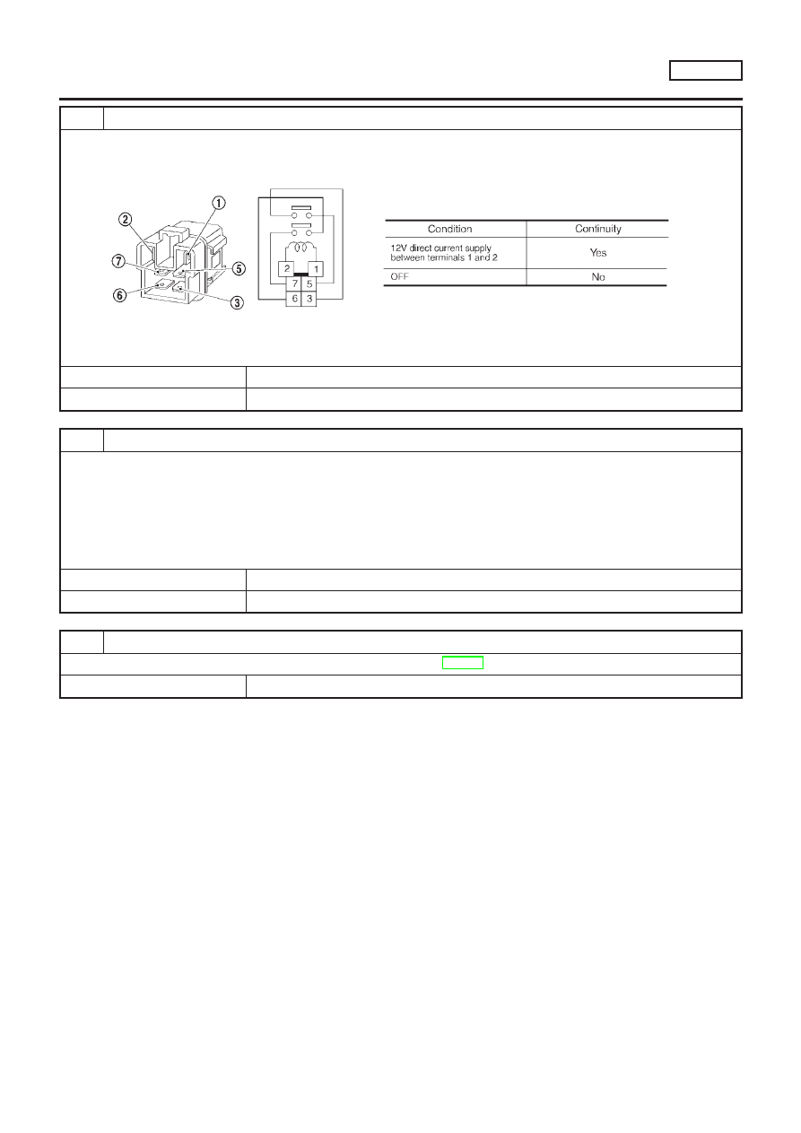
CHECK ECM RELAY
1. Apply 12V direct current between ECM relay terminals 1 and 2.
2. Check continuity between relay terminals 3 and 5, 6 and 7.
SEF296X
OK or NG
OK
©
GO TO 17.
NG
©
Replace ECM relay.
17
CHECK ECM GROUND CIRCUIT FOR OPEN AND SHORT-II
1. Turn ignition switch “OFF”.
2. Disconnect ECM harness connector.
3. Check harness continuity between ECM terminals 48, 57, 106, 108 and engine ground.
Refer to WIRING DIAGRAM.
Continuity should exist.
4. Also check harness for short to power.
OK or NG
OK
©
GO TO 18.
NG
©
Repair open circuit or short to power in harness or connectors.
18
CHECK INTERMITTENT INCIDENT
Refer to “TROUBLE DIAGNOSIS FOR INTERMITTENT INCIDENT”, EC-145.
©
INSPECTION END
TROUBLE DIAGNOSIS FOR POWER SUPPLY
QG18DE
Main Power Supply and Ground Circuit (Cont’d)
EC-153