Nissan Almera Tino V10 (2001 year). Manual - part 36
TERMI-
NAL
NO.
WIRE
COLOR
ITEM
CONDITION
DATA (DC Voltage)
35
36
37
38
L/W
PU
L/R
GY/R
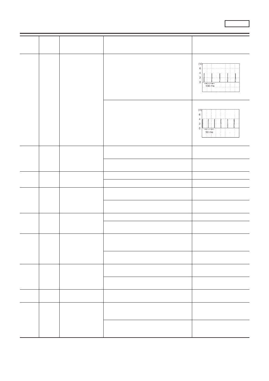
Ignition signal (No. 1)
Ignition signal (No. 2)
Ignition signal (No. 3)
Ignition signal (No. 4)
[Engine is running]
+
Warm-up condition
+
Idle speed
0 - 0.2V
SEF971W
[Engine is running]
+
Engine speed is 2,000 rpm
0.2 - 0.4V
SEF972W
40
Y/PU
Throttle position switch
(Closed position)
(where fitted)
[Engine is running]
+
Accelerator pedal released
BATTERY VOLTAGE
(11 - 14V)
[Engine is running]
+
Accelerator pedal depressed
Approximately 0V
41
B/Y
Start signal
[Ignition switch “ON”]
Approximately 0V
[Ignition switch “START”]
9 - 12V
42
G/OR
PNP switch
[Ignition switch “ON”]
+
Gear position is “Neutral position”
Approximately 0V
[Ignition switch “ON”]
+
Except the above gear position
Approximately 5V
43
B/R
Ignition switch
[Ignition switch “OFF”]
0V
[Ignition switch “ON”]
BATTERY VOLTAGE
(11 - 14V)
44
L/R
Air conditioner switch
[Engine is running]
+
Both air conditioner switch and blower switch
are “ON” (Compressor operates)
Approximately 0V
[Engine is running]
+
Air conditioner switch is “OFF”
Approximately 5V
46
PU/W
Power steering oil pres-
sure switch
[Engine is running]
+
Steering wheel is fully turned
Approximately 0V
[Engine is running]
+
Steering wheel is not turned
Approximately 5V
48
B
ECM ground
[Engine is running]
+
Idle speed
Engine ground
50
L/B
Electrical load signal
(Headlamp and
Rear defogger)
[Engine is running]
+
Headlamp switch or rear defogger switch is
“ON”
BATTERY VOLTAGE
(11 - 14V)
[Engine is running]
+
Headlamp switch and rear defogger switch are
“OFF”
Approximately 0V
TROUBLE DIAGNOSIS — GENERAL DESCRIPTION
QG18DE
ECM Terminals and Reference Value (Cont’d)
EC-137