Nissan Almera Tino V10 (2001 year). Manual - part 33
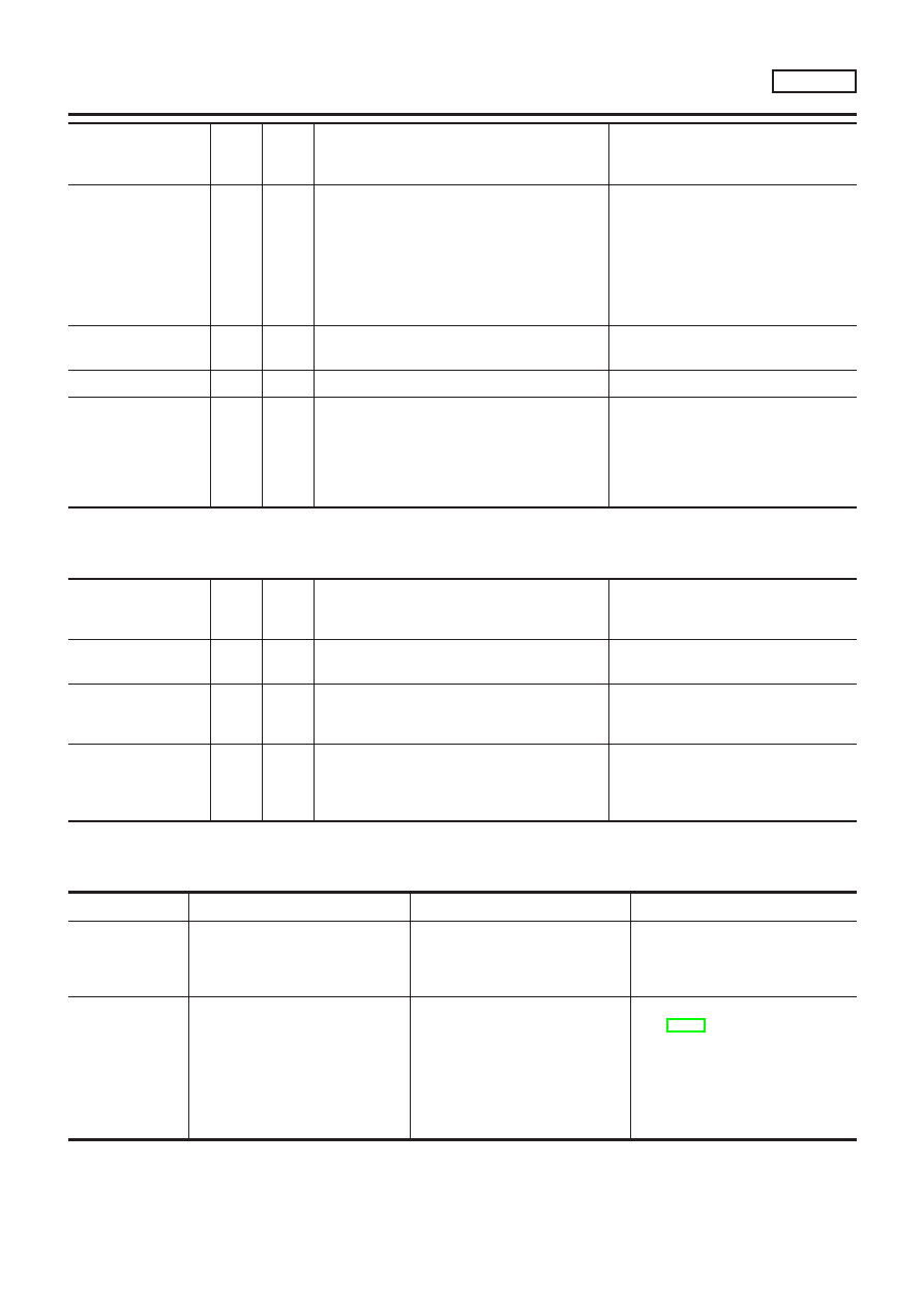
Monitored item [Unit]
ECM
input
signals
Main
signals
Description
Remarks
IDL A/V LEARN
+
Display the condition of idle air volume learn-
ing
YET ... Idle air volume learning has not been
performed yet.
CMPLT ... Idle air volume learning has
already been performed successfully.
INCMP ... Idle air volume learning has not
been performed successfully.
TRVL AFTER MIL
[km] or [Mile]
+
Distance traveled while MI is activated
VOLTAGE [V]
+
Voltage measured by the voltage probe.
PULSE
[msec] or [Hz] or [%]
+
Pulse width, frequency or duty cycle mea-
sured by the pulse probe.
+
Only “#” is displayed if item is
unable to be measured.
+
Figures with “#”s are temporary
ones. They are the same figures as
an actual piece of data which was
just previously measured.
NOTE:
Any monitored item that does not match the vehicle being diagnosed is deleted from the display automatically.
DATA MONITOR (SPEC) MODE
NLEC0034S11
Monitored item [Unit]
ECM
input
signals
Main
signals
Description
Remarks
MAS A/F SE-B1 [V]
j
j
+
The signal voltage of the mass air flow sen-
sor specification is displayed.
+
When the engine is running, specifi-
cation range is indicated.
B/FUEL SCHDL
[msec]
+
“Base fuel schedule” indicates the fuel injec-
tion pulse width programmed into ECM, prior
to any learned on board correction.
+
When the engine is running, specifi-
cation range is indicated.
A/F ALPHA-B1 [%]
j
+
Indicates the mean value of the air-fuel ratio
feedback correction factor per cycle.
+
When the engine is running, specifi-
cation range is indicated.
+
This data also includes the data for
the air-fuel ratio learning control.
NOTE:
Any monitored item that does not match the vehicle being diagnosed is deleted from the display automatically.
ACTIVE TEST MODE
NLEC0034S07
TEST ITEM
CONDITION
JUDGEMENT
CHECK ITEM (REMEDY)
FUEL INJEC-
TION
+
Engine: Return to the original
trouble condition
+
Change the amount of fuel injec-
tion using CONSULT-II.
If trouble symptom disappears, see
CHECK ITEM.
+
Harness and connector
+
Fuel injectors
+
Heated oxygen sensor 1 (front)
IGNITION TIM-
ING
+
Engine: Return to the original
trouble condition
+
Timing light: Set
+
Retard the ignition timing using
CONSULT-II.
If trouble symptom disappears, see
CHECK ITEM.
+
“Idle Air Volume Leaning” (Refer
to EC-57.)
+
Camshaft position sensor
(PHASE)
+
Crankshaft position sensor
(POS)
+
Engine component parts and
installing conditions
ON BOARD DIAGNOSTIC SYSTEM DESCRIPTION
QG18DE
CONSULT-II (Cont’d)
EC-89