Nissan Almera Tino V10 (2001 year). Manual - part 31


  Index      Manuals     Nissan Almera Tino V10 (2001 year) - Service and Repair Manual


Search            copyright infringement  


Content      ..     29      30      31      32     ..


Nissan Almera Tino V10 (2001 year). Manual - part 31


SEF217Z

SEF454Y

SEF455Y

Idle Air Volume Learning

NLEC0562

DESCRIPTION

NLEC0562S01

“Idle Air Volume Learning” is an operation to learn the idle air vol-
ume that keeps each engine within the specific range. It must be
performed under any of the following conditions:

+

Each time IACV-AAC valve, throttle body or ECM is replaced.

+

Idle speed or ignition timing is out of specification.

PRE-CONDITIONING

NLEC0562S02

Before performing “Idle Air Volume Learning”, make sure that all of
the following conditions are satisfied.
Learning will be cancelled if any of the following conditions are
missed for even a moment.

+

Battery voltage: More than 12.9V (At idle)

+

Engine coolant temperature: 70 - 99°C (158 - 210°F)

+

PNP switch: ON

+

Electric load switch: OFF
(Air conditioner, headlamp, rear window defogger)

On vehicles equipped with daytime light systems, set lighting
switch to the 1st position to light only small lamps.

+

Cooling fan motor: Not operating

+

Steering wheel: Neutral (Straight-ahead position)

+

Vehicle speed: Stopped

+

Transmission: Warmed-up
M/T models, drive vehicle for 10 minutes.

OPERATION PROCEDURE

NLEC0562S03

With CONSULT-II

NLEC0562S0301

1.

Start engine and warm it up to normal operating temperature.

2.

Check that all items listed under the topic “PRE-CONDITION-
ING” (previously mentioned) are in good order.

3.

Turn ignition switch “OFF” and wait at least 9 seconds.

4.

Start the engine and let it idle for at least 28 seconds.

5.

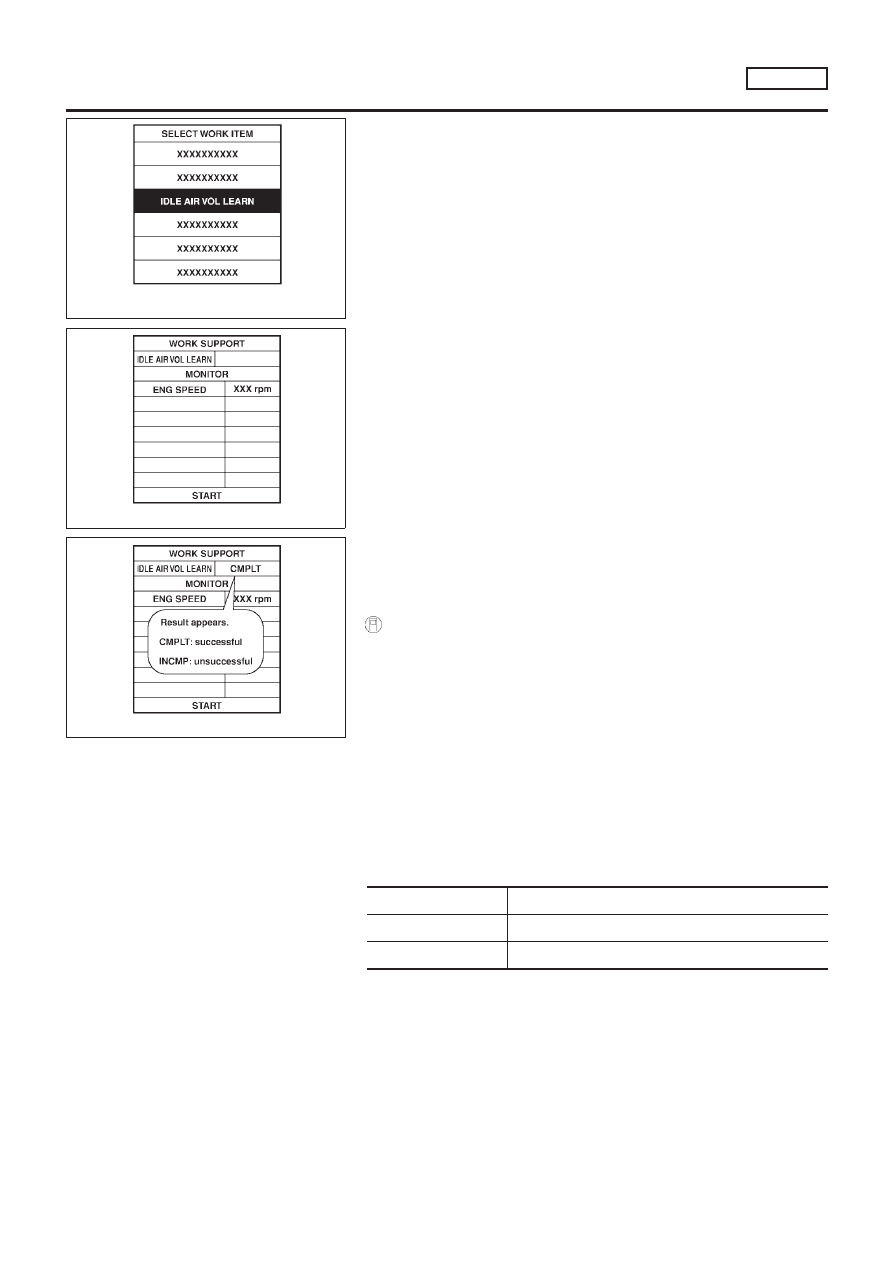
Select “IDLE AIR VOL LEARN” in “WORK SUPPORT” mode.

6.

Touch “START” and wait 20 seconds.

7.

Make sure that “CMPLT” is displayed on CONSULT-II screen.
If “INCMP” is displayed, “Idle Air Volume Learning” will not be
carried out successfully. In this case, find the cause of the
problem by referring to the NOTE below.

8.

Rev up the engine two or three times. Make sure that idle
speed and ignition timing are within specifications.

ITEM

SPECIFICATION

Idle speed

700

±

50 rpm

Ignition timing

8

±

2° BTDC

BASIC SERVICE PROCEDURE

QG18DE

Inspection Procedure (Cont’d)

EC-57

NEF309A

Without CONSULT-II

NLEC0562S0302

1.

Start engine and warm it up to normal operating temperature.

2.

Check that all items listed under the topic “PRE-CONDITION-
ING” (previously mentioned) are in good order.

3.

Turn ignition switch “OFF” and wait at least 9 seconds.

4.

Start the engine and let it idle for at least 28 seconds.

5.

Disconnect throttle position sensor harness connector (brown),
then reconnect it within 5 seconds.

6.

Wait 20 seconds.

7.

Make sure that idle speed is within specifications. If not, the
result will be incomplete. In this case, find the cause of the
problem by referring to the NOTE below.

8.

Rev up the engine two or three times. Make sure that idle
speed and ignition timing are within specifications.

ITEM

SPECIFICATION

Idle speed

700

±

50 rpm

Ignition timing

8

±

2° BTDC

NOTE:
If idle air volume learning cannot be performed successfully,
proceed as follows:
1)

Check that throttle valve is fully closed.

2)

Check that downstream of throttle valve is free from air
leakage.

3)

Adjust closed throttle position switch and reset memory.
(Refer to Basic Inspection, EC-99.)

4)

When the above three items check out OK, engine com-
ponent parts and their installation condition are question-
able. Check and eliminate the cause of the problem.

5)

If any of the following conditions occur after the engine
has started, eliminate the cause of the problem and per-
form “Idle air volume learning” all over again:

+

Engine stalls.

+

Erroneous idle.

+

Blown fuses related to the IACV-AAC valve system.

BASIC SERVICE PROCEDURE

QG18DE

Idle Air Volume Learning (Cont’d)

EC-58

Introduction

NLEC0029

MODELS WITH EURO-OBD SYSTEM

NLEC0029S01

The ECM has an on board diagnostic system which detects malfunctions related to engine sensors or actua-
tors. The ECM also records various emission-related diagnostic information including:

Diagnostic Trouble Code (DTC)

Mode 3 of ISO 15031-5

Freeze Frame data

Mode 2 of ISO 15031-5

System Readiness Test (SRT) code

Mode 1 of ISO 15031-5

1st Trip Diagnostic Trouble Code (1st Trip DTC)

Mode 7 of ISO 15031-5

1st Trip Freeze Frame data

Test values and Test limits

Mode 6 of ISO 15031-5

Calibration ID

Mode 9 of ISO 15031-5

The above information can be checked using procedures listed in the table below.

X: Applicable

—: Not applicable

DTC

1st trip DTC

Freeze Frame

data

1st trip Freeze

Frame data

SRT code

Test value

ECM*3

X

X*1

CONSULT-II

X

X

X

X

X

GST

X

X*2

X

X

X

*1: When DTC and 1st trip DTC simultaneously appear on the display, they cannot be clearly distinguished from each other.
*2: 1st trip DTCs for self-diagnoses concerning SRT items cannot be shown on the GST display.
*3: In diagnostic test mode II (Self-diagnostic results), DTC is displayed on MI. DTC uses a set of four digit numbers.

The malfunction indicator (MI) on the instrument panel lights up when the same malfunction is detected in two
consecutive trips (Two trip detection logic), or when the ECM enters fail-safe mode. (Refer to EC-123.)

MODELS WITHOUT EURO-OBD SYSTEM

NLEC0029S02

The ECM has an on board diagnostic system, which detects malfunctions related to engine sensors or actua-
tors. The ECM also records various emission-related diagnostic information including:

Diagnostic Trouble Code (DTC)

Freeze Frame data

1st Trip Diagnostic Trouble Code (1st Trip DTC)

1st Trip Freeze Frame data

The above information can be checked using procedures listed in the table below.

X: Applicable

—: Not applicable

DTC

1st trip DTC

Freeze Frame data

1st trip Freeze Frame

data

CONSULT-II

X

X

X

X

ECM*1

X

X*2

*1: In diagnostic test mode II (Self-diagnostic results), (1st trip) DTC is displayed on the MI by a set of four digit numbers.
*2: When the DTC and the 1st trip DTC appear on the display simultaneously, it is difficult to clearly distinguish one from the other.

Two Trip Detection Logic

NLEC0030

MODELS WITH EURO-OBD SYSTEM

NLEC0030S01

When a malfunction is detected for the first time, 1st trip DTC and 1st trip Freeze Frame data are stored in
the ECM memory. The MI will not light up at this stage <1st trip>.
If the same malfunction is detected again during the next drive, the DTC and Freeze Frame data are stored
in the ECM memory, and the MI lights up. The MI lights up at the same time when the DTC is stored <2nd
trip>.

ON BOARD DIAGNOSTIC SYSTEM DESCRIPTION

QG18DE

Introduction

EC-59

The “trip” in the “Two Trip Detection Logic” means a driving mode in which self-diagnosis is performed during
vehicle operation. Specific on board diagnostic items will cause the ECM to light up or blink the MI, and store
DTC and Freeze Frame data, even in the 1st trip, as shown below.

X: Applicable

—: Not applicable

Items

MI

DTC

1st trip DTC

1st trip

2nd trip

1st trip

displaying

2nd trip

displaying

1st trip

displaying

2nd trip

displaying

Blinking

Lighting

up

Blinking

Lighting

up

Misfire (Possible three way
catalyst damage)
— DTC: P0300 - P0304 is
being detected

X

X

Misfire (Possible three way
catalyst damage)
— DTC: P0300 - P0304 is
being detected

X

X

Fail-safe items (Refer to
EC-123.)

X

X*1

X*1

Except above

X

X

X

*1: Except “ECM”.

MODELS WITHOUT EURO-OBD SYSTEM

NLEC0030S02

When a malfunction is detected for the first time, 1st trip DTC and 1st trip Freeze Frame data are stored in
the ECM memory. <1st trip>
If the same malfunction is detected again during the next drive, the DTC and Freeze Frame data are stored
in the ECM memory. <2nd trip> The “trip” in the “Two Trip Detection Logic” means a driving mode in which
self-diagnosis is performed during vehicle operation. When the ECM enters the fail-safe mode (Refer to
EC-123), the DTC is stored in the ECM memory even in the 1st trip.

Emission-related Diagnostic Information

NLEC0031

MODELS WITH EURO-OBD SYSTEM

NLEC0031S01

DTC and 1st Trip DTC

NLEC0031S0101

The 1st trip DTC (whose number is the same as the DTC number) is displayed for the latest self-diagnostic
result obtained. If the ECM memory was cleared previously, and the 1st trip DTC did not reoccur, the 1st trip
DTC will not be displayed. If a malfunction is detected during the 1st trip, the 1st trip DTC is stored in the ECM
memory. The MI will not light up (two trip detection logic). If the same malfunction is not detected in the 2nd
trip (meeting the required driving pattern), the 1st trip DTC is cleared from the ECM memory. If the same mal-
function is detected in the 2nd trip, both the 1st trip DTC and DTC are stored in the ECM memory and the MI
lights up. In other words, the DTC is stored in the ECM memory and the MI lights up when the same malfunc-
tion occurs in two consecutive trips. If a 1st trip DTC is stored and a non-diagnostic operation is performed
between the 1st and 2nd trips, only the 1st trip DTC will continue to be stored. For malfunctions that blink or
light up the MI during the 1st trip, the DTC and 1st trip DTC are stored in the ECM memory.
Procedures for clearing the DTC and the 1st trip DTC from the ECM memory are described in “How to Erase
Emission-related Diagnostic Information”. Refer to EC-69.
For malfunctions in which 1st trip DTCs are displayed, refer to EC-68. These items are required by legal
regulations to continuously monitor the system/component. In addition, the items monitored non-continuously
are also displayed on CONSULT-II.
1st trip DTC is specified in Mode 7 of ISO 15031-5. 1st trip DTC detection occurs without lighting up the MI
and therefore does not warn the driver of a problem. However, 1st trip DTC detection will not prevent the
vehicle from being tested, for example during Inspection/Maintenance (I/M) tests.
When a 1st trip DTC is detected, check, print out or write down and erase (1st trip) DTC and Freeze Frame
data as specified in “Work Flow” procedure Step II, refer to page EC-97. Then perform “DTC Confirmation
Procedure” or “Overall Function Check” to try to duplicate the problem. If the malfunction is duplicated, the
item requires repair.
How to read DTC and 1st Trip DTC
DTC and 1st trip DTC can be read by the following methods.

With CONSULT-II/

With GST

ON BOARD DIAGNOSTIC SYSTEM DESCRIPTION

QG18DE

Two Trip Detection Logic (Cont’d)

EC-60

CONSULT-II or GST (Generic Scan Tool) Examples: P0340, P1320, P0705, P0750, etc.
These DTCs are prescribed by ISO 15031-6.
(CONSULT-II also displays the malfunctioning component or system.)

+

1st trip DTC No. is the same as DTC No.

+

Output of a DTC indicates a malfunction. However, Mode II and GST do not indicate whether the
malfunction is still occurring or has occurred in the past and has returned to normal.
CONSULT-II can identify malfunction status as shown below. Therefore, using CONSULT-II (if avail-
able) is recommended.

A sample of CONSULT-II display for DTC is shown below. DTC or 1st trip DTC of a malfunction is displayed
in SELF-DIAGNOSTIC RESULTS mode of CONSULT-II. Time data indicates how many times the vehicle was
driven after the last detection of a DTC.
If the DTC is being detected currently, the time data will be “0”.
If a 1st trip DTC is stored in the ECM, the time data will be “[1t]”.

SEF698X

Freeze Frame Data and 1st Trip Freeze Frame Data

NLEC0031S0102

The ECM records the driving conditions such as fuel system status, calculated load value, engine coolant
temperature, short term fuel trim, long term fuel trim, engine speed, vehicle speed, absolute throttle position,
base fuel schedule and intake air temperature at the moment a malfunction is detected.
Data which are stored in the ECM memory, along with the 1st trip DTC, are called 1st trip freeze frame data.
The data, stored together with the DTC data, are called freeze frame data and displayed on CONSULT-II or
GST. The 1st trip freeze frame data can only be displayed on the CONSULT-II screen, not on the GST. For
details, see EC-85.
Only one set of freeze frame data (either 1st trip freeze frame data or freeze frame data) can be stored in the
ECM. 1st trip freeze frame data is stored in the ECM memory along with the 1st trip DTC. There is no prior-
ity for 1st trip freeze frame data and it is updated each time a different 1st trip DTC is detected. However, once
freeze frame data (2nd trip detection/MI on) is stored in the ECM memory, 1st trip freeze frame data is no
longer stored. Remember, only one set of freeze frame data can be stored in the ECM. The ECM has the fol-
lowing priorities to update the data.

Priority

Items

1

Freeze frame data

Misfire — DTC: P0300 - P0304 (0300 - 0304)
Fuel Injection System Function — DTC: P0171 (0171), P0172 (0172)

2

Except the above items

3

1st trip freeze frame data

For example, the EGR malfunction (Priority: 2) was detected and the freeze frame data was stored in the 2nd
trip. After that when the misfire (Priority: 1) is detected in another trip, the freeze frame data will be updated
from the EGR malfunction to the misfire. The 1st trip freeze frame data is updated each time a different mal-
function is detected. There is no priority for 1st trip freeze frame data. However, once freeze frame data is
stored in the ECM memory, 1st trip freeze data is no longer stored (because only one freeze frame data or
1st trip freeze frame data can be stored in the ECM). If freeze frame data is stored in the ECM memory and
freeze frame data with the same priority occurs later, the first (original) freeze frame data remains unchanged
in the ECM memory.
Both 1st trip freeze frame data and freeze frame data (along with the DTCs) are cleared when the ECM
memory is erased. Procedures for clearing the ECM memory are described in “How to Erase Emission-related
Diagnostic Information”. Refer to EC-69.

ON BOARD DIAGNOSTIC SYSTEM DESCRIPTION

QG18DE

Emission-related Diagnostic Information (Cont’d)

EC-61

System Readiness Test (SRT) Code

NLEC0031S0103

System Readiness Test (SRT) code is specified in Mode 1 of ISO 15031-5.
As part of an emissions test for Inspection & Maintenance (I/M), certain states require the status of SRT be
used to indicate whether the ECM has completed self-diagnosis of major emission systems and components.
Completion must be verified in order for the emissions inspection to proceed.
If a vehicle is rejected for a State emissions inspection due to one or more SRT items indicating “INCMP”,
use the information in this Service Manual to set the SRT to “CMPLT”.
In most cases the ECM will automatically complete its self-diagnosis cycle during normal usage, and the SRT
status will indicate “CMPLT” for each application system. Once set as “CMPLT”, the SRT status remains
“CMPLT” until the self-diagnosis memory is erased.
Occasionally, certain portions of the self-diagnostic test may not be completed as a result of the customer’s
normal driving pattern; the SRT will indicate “INCMP” for these items.
NOTE:
The SRT will also indicate “INCMP” if the self-diagnosis memory is erased for any reason or if the ECM
memory power supply is interrupted for several hours.
If, during the state emissions inspection, the SRT indicates “CMPLT” for all test items, the inspector will con-
tinue with the emissions test. However, if the SRT indicates “INCMP” for one or more of the SRT items the
vehicle is returned to the customer untested.
NOTE:
If MI is “ON” during the state emissions inspection, the vehicle is also returned to the customer untested even
though the SRT indicates “CMPLT” for all test items. Therefore, it is important to check SRT (“CMPLT”) and
DTC (No DTCs) before the inspection.

SRT Item

NLEC0031S0107

The table below shows required self-diagnostic items to set the SRT to “CMPLT”.

SRT item

(CONSULT-II indica-

tion)

Perfor-

mance Pri-

ority*1

Required self-diagnostic items to set the SRT to “CMPLT”

Corresponding

DTC No.

CATALYST

3

Three way catalyst function

P0420

O2 SENSOR

3

Heated oxygen sensor 1 (front) (circuit)

P0130

Heated oxygen sensor 1 (front) (lean shift monitoring)

P0131

Heated oxygen sensor 1 (front) (rich shift monitoring)

P0132

Heated oxygen sensor 1 (front) (response monitoring)

P0133

Heated oxygen sensor 1 (front) (high voltage)

P0134

Heated oxygen sensor 2 (rear) (min. voltage monitoring)

P0137

Heated oxygen sensor 2 (rear) (max. voltage monitoring)

P0138

Heated oxygen sensor 2 (rear) (response monitoring)

P0139

Heated oxygen sensor 2 (rear) (high voltage)

P0140

O2 SEN HEATER

3

Heated oxygen sensor 1 heater (front)

P0135

Heated oxygen sensor 1 heater (rear)

P0141

EGR SYSTEM
(where fitted)

3

EGR function (close)

P0400

1

EGR function (open)

P1402

*1: If completion of several SRTs is required, perform driving patterns (DTC confirmation procedure), one by one based on the priority
for models with CONSULT-II.

SRT Set Timing

NLEC0031S0108

SRT is set as “CMPLT” after self-diagnosis has been performed one or more times. Completion of SRT is done
regardless of whether the result is OK or NG. The set timing is different between OK and NG results and is
shown in the table below.

ON BOARD DIAGNOSTIC SYSTEM DESCRIPTION

QG18DE

Emission-related Diagnostic Information (Cont’d)

EC-62

Self-diagnosis result

Example

Diagnosis

Ignition cycle

ON

OFF

ON

OFF

ON

OFF

ON

All OK

Case 1

P0400

OK (1)

— (1)

OK (2)

— (2)

P0402

OK (1)

— (1)

— (1)

OK (2)

P1402

OK (1)

OK (2)

— (2)

— (2)

SRT of EGR

“CMPLT”

“CMPLT”

“CMPLT”

“CMPLT”

Case 2

P0400

OK (1)

— (1)

— (1)

— (1)

P0402

— (0)

— (0)

OK (1)

— (1)

P1402

OK (1)

OK (2)

— (2)

— (2)

SRT of EGR

“INCMP”

“INCMP”

“CMPLT”

“CMPLT”

NG exists

Case 3

P0400

OK

OK

P0402

P1402

NG

NG

NG

(Consecutive

NG)

(1st trip)

DTC

1st trip DTC

1st trip DTC

DTC

(= MIL “ON”)

SRT of EGR

“INCMP”

“INCMP”

“INCMP”

“CMPLT”

OK: Self-diagnosis is carried out and the result is OK.
NG: Self-diagnosis is carried out and the result is NG.
—: Self-diagnosis is not carried out.

When all SRT related self-diagnoses showed OK results in a single cycle (Ignition OFF-ON-OFF), the SRT
will indicate “CMPLT”.

Case 1 above

When all SRT related self-diagnoses showed OK results through several different cycles, the SRT will indi-
cate “CMPLT” at the time the respective self-diagnoses have at least one OK result.

Case 2 above

If one or more SRT related self-diagnoses showed NG results in 2 consecutive cycles, the SRT will also indi-
cate “CMPLT”.

Case 3 above

The table above shows that the minimum number of cycles for setting SRT as “INCMP” is one (1) for each
self-diagnosis (Case 1 & 2) or two (2) for one of self-diagnoses (Case 3). However, in preparation for the state
emissions inspection, it is unnecessary of each self-diagnosis to be executed twice (Case 3) for the following
reasons:

+

The SRT will indicate “CMPLT” at the time the respective self-diagnoses have one (1) OK result.

+

The emissions inspection requires “CMPLT” of the SRT only with OK self-diagnosis results.

+

When, during SRT driving pattern, 1st trip DTC (NG) is detected prior to “CMPLT” of SRT, the self-diag-
nosis memory must be erased from ECM after repair.

+

If the 1st trip DTC is erased, all the SRT will indicate “INCMP”.

NOTE:
SRT can be set as “CMPLT” together with the DTC(s). Therefore, DTC check must always be carried out prior
to the state emission inspection even though the SRT indicates “CMPLT”.

SRT Service Procedure

NLEC0031S0109

If a vehicle has failed the state emissions inspection due to one or more SRT items indicating “INCMP”, review
the flowchart diagnostic sequence on the next page.

ON BOARD DIAGNOSTIC SYSTEM DESCRIPTION

QG18DE

Emission-related Diagnostic Information (Cont’d)

EC-63

SEF573XB

*1

EC-60

*2

EC-64

*3

EC-65

How to Display SRT Code

NLEC0031S0110

1.

With CONSULT-II

Selecting “SRT STATUS” in “DTC CONFIRMATION” mode with CONSULT-II.
For items whose SRT codes are set, a “CMPLT” is displayed on the CONSULT-II screen; for items whose
SRT codes are not set, “INCMP” is displayed as shown below.

ON BOARD DIAGNOSTIC SYSTEM DESCRIPTION

QG18DE

Emission-related Diagnostic Information (Cont’d)

EC-64

SEF821Y

2.

With GST

Selecting Mode 1 with GST (Generic Scan Tool)

How to Set SRT Code

NLEC0031S0111

To set all SRT codes, self-diagnosis for the items indicated above must be performed one or more times. Each
diagnosis may require a long period of actual driving under various conditions.

With CONSULT-II

Perform corresponding DTC Confirmation Procedure one by one based on “Performance Priority” in the table
on EC-122.

Without CONSULT-II

The most efficient driving pattern in which SRT codes can be properly set is explained on the next page. The
driving pattern should be performed one or more times to set all SRT codes.

ON BOARD DIAGNOSTIC SYSTEM DESCRIPTION

QG18DE

Emission-related Diagnostic Information (Cont’d)

EC-65

Driving Pattern

=NLEC0031S0112

NEF321A

ON BOARD DIAGNOSTIC SYSTEM DESCRIPTION

QG18DE

Emission-related Diagnostic Information (Cont’d)

EC-66

+

The time required for each diagnosis varies with road surface conditions, weather, altitude, individual driv-
ing habits, etc.
Zone A refers to the range where the time required, for the diagnosis under normal conditions*, is the
shortest. Zone B refers to the range where the diagnosis can still be performed if the diagnosis is not
completed within zone A.

*: Normal conditions refer to the following:

Sea level

Flat road

Ambient air temperature: 20 - 30°C (68 - 86°F)

Diagnosis is performed as quickly as possible under normal conditions.
Under different conditions [For example: ambient air temperature other than 20 - 30°C (68 - 86°F)], diag-
nosis may also be performed.

Pattern 1:

+

The engine is started at the engine coolant temperature of −10 to 35°C (14 to 95°F) (where the volt-
age between the ECM terminals 70 and 58 is 3.0 - 4.3V).

+

The engine must be operated at idle speed until the engine coolant temperature is greater than 70°C
(158°F) (where the voltage between the ECM terminals 70 and 58 is lower than 1.4V).

+

The engine is started at the fuel tank temperature of warmer than 0°C (32°F) (where the voltage
between the ECM terminal 82 and ground is less than 4.1V).

Pattern 2:

+

When steady-state driving is performed again even after it is interrupted, each diagnosis can be conducted.
In this case, the time required for diagnosis may be extended.

*1: Depress the accelerator pedal until vehicle speed is 90 km/h (56 MPH), then release the accelerator pedal
and keep it released for more than 10 seconds. Depress the accelerator pedal until vehicle speed is 90 km/h
(56 MPH) again.
*2: Checking the vehicle speed with CONSULT-II or GST is advised.
Suggested upshift speeds
Shown below are suggested vehicle speeds for shifting into a higher gear. These suggestions relate to fuel
economy and vehicle performance. Actual upshift speeds will vary according to road conditions, the weather
and individual driving habits.

Gear change

ACCEL shift point
km/h (MPH)

1st to 2nd

15 (9)

2nd to 3rd

35 (22)

3rd to 4th

50 (31)

4th to 5th

70 (43)

Test Value and Test Limit (GST only — not applicable to CONSULT-II)

NLEC0031S0104

The following is the information specified in Mode 6 of ISO 15031-5.
The test value is a parameter used to determine whether a system/circuit diagnostic test is “OK” or “NG” while
being monitored by the ECM during self-diagnosis. The test limit is a reference value which is specified as the
maximum or minimum value and is compared with the test value being monitored.
Items for which these data (test value and test limit) are displayed are the same as SRT code items (14 test
items).
These data (test value and test limit) are specified by Test ID (TID) and Component ID (CID) and can be dis-
played on the GST screen.

X: Applicable

—: Not applicable

SRT item

Self-diagnostic test item

Test value (GST display)

Test limit

Application

TID

CID

CATALYST

Three way catalyst function

01H

01H

Max.

X

02H

81H

Min.

X

ON BOARD DIAGNOSTIC SYSTEM DESCRIPTION

QG18DE

Emission-related Diagnostic Information (Cont’d)

EC-67

SRT item

Self-diagnostic test item

Test value (GST display)

Test limit

Application

TID

CID

HO2S

Heated oxygen sensor 1

(front)

09H

04H

Max.

X

0AH

84H

Min.

X

0BH

04H

Max.

X

0CH

04H

Max.

X

0DH

04H

Max.

X

Heated oxygen sensor 2

(rear)

19H

86H

Min.

X

1AH

86H

Min.

X

1BH

06H

Max.

X

1CH

06H

Max.

X

HO2S HTR

Heated oxygen sensor 1

heater (front)

29H

08H

Max.

X

2AH

88H

Min.

X

Heated oxygen sensor 2

heater (rear)

2DH

0AH

Max.

X

2EH

8AH

Min.

X

EGR SYSTEM

(where fitted)

EGR function

31H

8CH

Min.

X

32H

8CH

Min.

X

33H

8CH

Min.

X

34H

8CH

Min.

X

35H

0CH

Max.

X

Emission-related Diagnostic Information Items

NLEC0031S0105

X: Applicable

—: Not applicable

Items

(CONSULT-II screen terms)

DTC*1

SRT code

Test value/Test

limit

(GST only)

1st trip DTC*1

Reference page

NO SELF DIAGNOSTIC FAIL-
URE INDICATED

P0000

MAF SEN/CIRCUIT

P0100

X

EC-154

AIR TEMP SEN/CIRC

P0110

X

EC-161

COOLANT T SEN/CIRC

P0115

X

EC-169

THRTL POS SEN/CIRC

P0120

X

EC-175

HO2S1 (B1)

P0130

X

X

X*2

EC-184

HO2S1 (B1)

P0131

X

X

X*2

EC-192

HO2S1 (B1)

P0132

X

X

X*2

EC-198

HO2S1 (B1)

P0133

X

X

X*2

EC-204

HO2S1 (B1)

P0134

X

X

X*2

EC-214

HO2S1 HTR (B1)

P0135

X

X

X*2

EC-221

HO2S2 (B1)

P0137

X

X

X*2

EC-227

HO2S2 (B1)

P0138

X

X

X*2

EC-237

HO2S2 (B1)

P0139

X

X

X*2

EC-246

ON BOARD DIAGNOSTIC SYSTEM DESCRIPTION

QG18DE

Emission-related Diagnostic Information (Cont’d)

EC-68

Items

(CONSULT-II screen terms)

DTC*1

SRT code

Test value/Test

limit

(GST only)

1st trip DTC*1

Reference page

HO2S2 (B1)

P0140

X

X

X*2

EC-256

HO2S2 HTR (B1)

P0141

X

X

X*2

EC-263

FUEL SYS-LEAN/BK1

P0171

X

EC-269

FUEL SYS-RICH/BK1

P0172

X

EC-277

MULTI CYL MISFIRE

P0300

X

EC-285

CYL 1 MISFIRE

P0301

X

EC-285

CYL 2 MISFIRE

P0302

X

EC-285

CYL 3 MISFIRE

P0303

X

EC-285

CYL 4 MISFIRE

P0304

X

EC-285

KNOCK SEN/CIRC-B1

P0325

EC-291

CKP SEN/CIRCUIT (POS)

P0335

X

EC-295

CMP SEN/CIRCUIT (PHS)

P0340

X

EC-302

EGR SYSTEM (where fitted)

P0400

X

X

X*2

EC-310

EGR VOL CONT/V CIRC
(where fitted)

P0403

X

EC-319

TW CATALYST SYS-B1

P0420

X

X

X*2

EC-327

PURG VOLUME CONT/V

P0443

X

EC-332

VEH SPEED SEN/CIRC

P0500

X

EC-338

IACV/AAC VLV/CIRC

P0505

X

EC-343

CLOSED TP SW/CIRC
(where fitted)

P0510

X

EC-352

ECM

P0605

X

EC-358

INT/V TIM V/CIR-B1

P1111

X

EC-360

SWIRL CONT SOL/V
(where fitted)

P1131

X

EC-366

ENG OVER TEMP

P1217

X

EC-373

EGR TEMP SEN/CIRC
(where fitted)

P1401

X

EC-386

EGR SYSTEM (where fitted)

P1402

X

X

X*2

EC-393

P-N POS SW/CIRCUIT

P1706

X

EC-402

*1: 1st trip DTC No. is the same as DTC No.
*2: These are not displayed with GST.

How to Erase Emission-related Diagnostic Information

NLEC0031S0106

How to Erase DTC (With CONSULT-II)

1) If the ignition switch stays “ON” after repair work, be sure to turn ignition switch “OFF” once. Wait at least

9 seconds and then turn it “ON” (engine stopped) again.

2) Touch “ENGINE”.
3) Touch “SELF-DIAG RESULTS”.
4) Touch “ERASE”. (The DTC in the ECM will be erased.)

ON BOARD DIAGNOSTIC SYSTEM DESCRIPTION

QG18DE

Emission-related Diagnostic Information (Cont’d)

EC-69

SEF630Z

The emission-related diagnostic information can be erased by selecting “ERASE” in the “SELF-DIAG
RESULTS” mode with CONSULT-II.
How to Erase DTC (

With GST)

1) If the ignition switch stays “ON” after repair work, be sure to turn ignition switch “OFF” once. Wait at least

9 seconds and then turn it “ON” (engine stopped) again.

2) Select Mode 4 with GST (Generic Scan Tool).
The emission-related diagnostic information can be erased by selecting Mode 4 with GST (Generic Scan Tool).
NOTE:

+

If the battery is disconnected, the emission-related diagnostic information will be lost after approx.
24 hours.

+

Erasing the emission-related diagnostic information using CONSULT-II or GST is easier and
quicker than switching the mode using the data link connector.

+

The following data are cleared when the ECM memory is erased.

1) Diagnostic trouble codes
2) 1st trip diagnostic trouble codes
3) Freeze frame data
4) 1st trip freeze frame data
5) System readiness test (SRT) codes
6) Test values
7) Distance traveled while MI is activated
8) Others
Actual work procedures are explained using a DTC as an example. Be careful so that not only the DTC, but
all of the data listed above, are cleared from the ECM memory during work procedures.

MODELS WITHOUT EURO-OBD SYSTEM

NLEC0031S07

DTC and 1st Trip DTC

NLEC0031S0701

The 1st trip DTC (whose number is the same as the DTC number) is displayed for the latest self-diagnostic
result obtained. If the ECM memory was cleared previously, and the 1st trip DTC did not reoccur, the 1st trip
DTC will not be displayed.
If a malfunction is detected during the 1st trip, the 1st trip DTC is stored in the ECM memory. If the same mal-
function is not detected in the 2nd trip (meeting the required driving pattern), the 1st trip DTC is cleared from
the ECM memory. If the same malfunction is detected in the 2nd trip, both the 1st trip DTC and DTC are stored
in the ECM memory. In other words, the DTC is stored in the ECM memory when the same malfunction occurs
in two consecutive trips. If a 1st trip DTC is stored and a non-diagnostic operation is performed between the
1st and 2nd trips, only the 1st trip DTC will continue to be stored. For fail-safe items, the DTC is stored in the
ECM memory even in the 1st trip.

ON BOARD DIAGNOSTIC SYSTEM DESCRIPTION

QG18DE

Emission-related Diagnostic Information (Cont’d)

EC-70

Procedures for clearing the DTC and the 1st trip DTC from the ECM memory are described in “How to Erase
Emission-related Diagnostic Information”, EC-71.
When a (1st trip) DTC is detected, check, print out or write down and erase (1st trip) DTC and Freeze Frame
data as specified in “Work Flow” procedure Step II, refer to EC-97. Then perform “DTC Confirmation Proce-
dure” or “Overall Function Check” to try to duplicate the problem. If the malfunction is duplicated, the item
requires repair.
How to Read DTC and 1st Trip DTC
DTC and 1st trip DTC can be read by the following methods.

Without CONSULT-II

ECM displays the DTC by a set of four digit numbers with MI illumination in the diagnostic test mode II (Self-
diagnostic results). Example: 0100, 0115, 0340, 1335, etc.

With CONSULT-II

CONSULT-II displays the DTC in “SELF-DIAG RESULTS” mode. Examples: P0100, P0115, P0340, P1335,
etc.
(CONSULT-II also displays the malfunctioning component or system.)

+

1st trip DTC No. is the same as DTC No.

+

Output of a DTC indicates a malfunction. However, ECM in the diagnostic test mode II (Self-diag-
nostic results) does not indicate whether the malfunction is still occurring or has occurred in the
past and has returned to normal. CONSULT-II can identify malfunction status as shown below.
Therefore, the use of CONSULT-II (if available) is recommended.

A sample CONSULT-II display for DTC and 1st trip DTC is shown below. DTC or 1st trip DTC of a malfunc-
tion is displayed in the SELF-DIAGNOSTIC RESULTS mode of CONSULT-II. Time data indicates how many
times the vehicle was driven after the last detection of a DTC.
If the DTC is being detected currently, the time data will be “0”.
If a 1st trip DTC is stored in the ECM, the time data will be “[1t]”.

SEF992X

Freeze Frame Data and 1st Trip Freeze Frame Data

NLEC0031S0702

The ECM records the driving conditions such as fuel system status, calculated load value, engine coolant
temperature, short term fuel trim, long term fuel trim, engine speed, vehicle speed, throttle valve opening, base
fuel schedule and intake air temperature at the moment a malfunction is detected.
Data which are stored in the ECM memory, along with the 1st trip DTC, are called 1st trip freeze frame data.
The data, stored together with the DTC data, are called freeze frame data and displayed on CONSULT-II. For
details, see EC-85.
Only one set of freeze frame data (either 1st trip freeze frame data or freeze frame data) can be stored in the
ECM. 1st trip freeze frame data is stored in the ECM memory along with the 1st trip DTC. There is no prior-
ity for 1st trip freeze frame data and it is updated each time a different 1st trip DTC is detected. However, once
freeze frame data is stored in the ECM memory, 1st trip freeze frame data is no longer stored. Remember,
only one set of freeze frame data can be stored in the ECM.
If freeze frame data is stored in the ECM memory and another freeze frame data occurs later, the first (origi-
nal) freeze frame data remains unchanged in the ECM memory.
Both 1st trip freeze frame data and freeze frame data (along with the DTCs) are cleared when the ECM
memory is erased. Procedures for clearing the ECM memory are described in “How to Erase Emission-related
Diagnostic Information”, EC-71.

How to Erase Emission-related Diagnostic Information

NLEC0031S0706

How to Erase DTC (

With CONSULT-II)

1) If the ignition switch stays “ON” after repair work, be sure to turn ignition switch “OFF” once. Wait at least

10 seconds and then turn it “ON” (engine stopped) again.

ON BOARD DIAGNOSTIC SYSTEM DESCRIPTION

QG18DE

Emission-related Diagnostic Information (Cont’d)

EC-71

2) Touch “ENGINE”.
3) Touch “SELF-DIAG RESULTS”.
4) Touch “ERASE”. (The DTC in the ECM will be erased.)

SEF993XA

The emission related diagnostic information in the ECM can be erased by selecting “ERASE” in the “SELF-
DIAG RESULTS” mode with CONSULT-II.
How to Erase DTC (

Without CONSULT-II)

1) If the ignition switch stays “ON” after repair work, be sure to turn ignition switch “OFF” once. Wait at least

10 seconds and then turn it “ON” (engine stopped) again.

2) Change the diagnostic test mode from Mode II to Mode I by using the data link connector. (See EC-75.)
The emission related diagnostic information in the ECM can be erased by changing the diagnostic test mode.

+

If the battery is disconnected, the emission-related diagnostic information will be lost after approx.
24 hours.

+

Erasing the emission-related diagnostic information using CONSULT-II is easier and quicker than
switching the diagnostic test mode using the data link connector.

+

The following data are cleared when the ECM memory is erased.

1) Diagnostic trouble codes
2) 1st trip diagnostic trouble codes
3) Freeze frame data
4) 1st trip freeze frame data
5) Others
Actual work procedures are explained using a DTC as an example. Be careful so that not only the DTC, but
all of the data listed above, are cleared from the ECM memory during work procedures.

SEF543X

NATS (Nissan Anti-theft System)

NLEC0591

+

If the security indicator lights up with the ignition switch
in the “ON” position or “NATS MALFUNCTION” is dis-
played on “SELF-DIAG RESULTS” screen, perform self-
diagnostic results mode with CONSULT-II using NATS pro-
gram card. Refer to NATS (Nissan Anti-Theft System) in EL
section.

+

Confirm no self-diagnostic results of NATS is displayed
before touching “ERASE” in “SELF-DIAG RESULTS”
mode with CONSULT-II.

+

When replacing ECM, initialization of NATS system and

ON BOARD DIAGNOSTIC SYSTEM DESCRIPTION

QG18DE

Emission-related Diagnostic Information (Cont’d)

EC-72


Content      ..     29      30      31      32     ..