Nissan Almera Tino V10 (2001 year). Manual - part 30


  Index      Manuals     Nissan Almera Tino V10 (2001 year) - Service and Repair Manual


Search            copyright infringement  


Content      ..     28      29      30      31     ..


Nissan Almera Tino V10 (2001 year). Manual - part 30


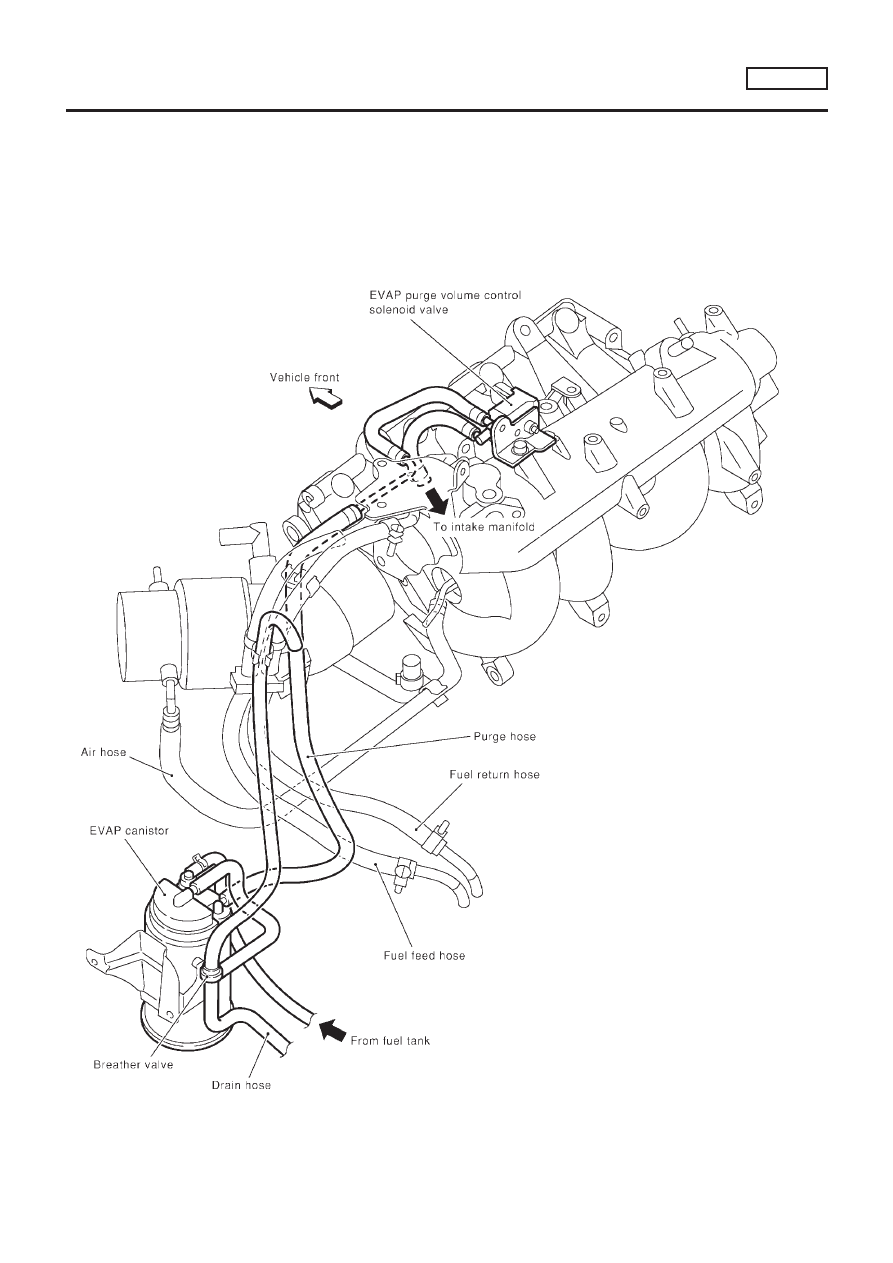
EVAPORATIVE EMISSION LINE DRAWING

=NLEC0020

NOTE:
Do not use soapy water or any type of solvent while installing vacuum hoses or purge hoses.

SEF600Y

ENGINE AND EMISSION BASIC CONTROL SYSTEM

DESCRIPTION

QG18DE

Evaporative Emission System (Cont’d)

EC-41

Positive Crankcase Ventilation

DESCRIPTION

NLEC0022

SEF921W

This system returns blow-by gas to the intake collector.
The positive crankcase ventilation (PCV) valve is provided to conduct crankcase blow-by gas to the intake
manifold.
During partial throttle operation of the engine, the intake manifold sucks the blow-by gas through the PCV
valve.
Normally, the capacity of the valve is sufficient to handle any blow-by and a small amount of ventilating air.
The ventilating air is then drawn from the air duct into the crankcase. In this process the air passes through
the hose connecting air inlet tubes to rocker cover.
Under full-throttle condition, the manifold vacuum is insufficient to draw the blow-by flow through the valve.
The flow goes through the hose connection in the reverse direction.
On vehicles with an excessively high blow-by, the valve does not meet the requirement. This is because some
of the flow will go through the hose connection to the intake collector under all conditions.

SEF244Q

INSPECTION

NLEC0023

PCV (Positive Crankcase Ventilation) Valve

NLEC0023S01

With engine running at idle, remove PCV valve from breather sepa-
rator. A properly working valve makes a hissing noise as air passes
through it. A strong vacuum should be felt immediately when a fin-
ger is placed over the valve inlet.

ET277

Ventilation Hose

NLEC0023S02

1.

Check hoses and hose connections for leaks.

2.

Disconnect all hoses and clean with compressed air. If any
hose cannot be freed of obstructions, replace.

ENGINE AND EMISSION BASIC CONTROL SYSTEM

DESCRIPTION

QG18DE

Positive Crankcase Ventilation

EC-42

SEF094Y

SEF214Y

Fuel Pressure Release

NLEC0024

Before disconnecting fuel line, release fuel pressure from fuel
line to eliminate danger.

WITH CONSULT-II

NLEC0024S01

1.

Start engine.

2.

Perform “FUEL PRESSURE RELEASE” in “WORK SUP-
PORT” mode with CONSULT-II.

3.

After engine stalls, crank it two or three times to release all fuel
pressure.

4.

Turn ignition switch OFF.

JEF086Y

WITHOUT CONSULT-II

NLEC0024S02

1.

Remove fuse for fuel pump. Refer to fuse block cover for fuse
location.

2.

Start engine.

3.

After engine stalls, crank it two or three times to release all fuel
pressure.

4.

Turn ignition switch OFF and reconnect fuel pump fuse.

JEF087Y

Fuel Pressure Check

NLEC0025

+

When reconnecting fuel line, always use new clamps.

+

Make sure that clamp screw does not contact adjacent
parts.

+

Use a torque driver to tighten clamps.

+

Use Pressure Gauge to check fuel pressure.

+

Do not perform fuel pressure check with system operat-
ing. Fuel pressure gauge may indicate false readings.

1.

Release fuel pressure to zero.

2.

Disconnect fuel hose between fuel filter and fuel tube (engine
side).

3.

Install pressure gauge between fuel filter and fuel tube.

4.

Start engine and check for fuel leakage.

5.

Read the indication of fuel pressure gauge.

At idle speed:

With vacuum hose connected

Approximately 235 kPa (2.35 bar, 2.4 kg/cm

2

, 34

psi)

With vacuum hose disconnected

Approximately 294 kPa (2.94 bar, 3.0 kg/cm

2

, 43

psi)

BASIC SERVICE PROCEDURE

QG18DE

Fuel Pressure Release

EC-43

If results are unsatisfactory, perform Fuel Pressure Regulator
Check, EC-44.

SEF718B

Fuel Pressure Regulator Check

NLEC0026

1.

Stop engine and disconnect fuel pressure regulator vacuum
hose from intake manifold.

2.

Plug intake manifold with a rubber cap.

3.

Connect variable vacuum source to fuel pressure regulator.

4.

Start engine and read indication of fuel pressure gauge as
vacuum is changed.

Fuel pressure should decrease as vacuum increases. If results
are unsatisfactory, replace fuel pressure regulator.

JEF088Y

SEF927W

Injector

REMOVAL AND INSTALLATION

NLEC0027

1.

Release fuel pressure to zero.

2.

Remove fuel tube assemblies in numerical sequence as
shown in the Figure at left.

3.

Expand and remove clips securing fuel injectors.

4.

Extract fuel injectors straight from fuel tubes.

+

Be careful not to damage injector nozzles during removal.

+

Do not bump or drop fuel injectors.

5.

Install fuel injectors.
Carefully install O-rings, including the one used with the pres-
sure regulator.

+

Lubricate O-rings with a smear of engine oil.

+

Be careful not to damage O-rings with service tools or
finger nails or clips. Do not expand or twist O-rings.

+

Discard old clips; replace with new ones.

6.

Position clips in grooves on fuel injectors.

+

Make sure that protrusions of fuel injectors are aligned
with cutouts of clips after installation.

BASIC SERVICE PROCEDURE

QG18DE

Fuel Pressure Regulator Check

EC-44

JEF089Y

7.

Align protrusions of fuel tubes with those of fuel injectors.
Insert fuel injectors straight into fuel tubes.

8.

After properly inserting fuel injectors, check to make sure that
fuel tube protrusions are engaged with those of fuel injectors,
and that flanges of fuel tubes are engaged with clips.

JEF815Y

9.

Tighten fuel tube assembly mounting nuts in numerical
sequence (indicated in the Figure at left) and in two stages.

: Tightening torque N·m (kg-m, ft-lb)

1st stage:

12 - 13 (1.2 - 1.4, 9 - 10)

2nd stage:

17 - 23 (1.7 - 2.4, 13 - 17)

10. Insert fuel hoses into fuel tubes so that ends of fuel hoses butt

up against fuel tubes; fasten with clamps, avoiding bulges.

CAUTION:

After properly connecting fuel tube assembly to injector and
fuel hose, check connection for fuel leakage.

BASIC SERVICE PROCEDURE

QG18DE

Injector (Cont’d)

EC-45

SEF058Y

How to Check Idle Speed and Ignition Timing

NLEC0028

IDLE SPEED

NLEC0028S05

+

Using CONSULT-II
Check idle speed in “DATA MONITOR” mode with CONSULT-
II.

+

With GST
Check idle speed in “MODE 1” with GST.

JEF150Y

JEF438Z

IGNITION TIMING

NLEC0028S06

Any of following two methods may be used.

+

Method A

a)

Attach timing light to loop wire or, combine the three No. 1
ignition coil harnesses and attach the timing light sensor
(attach from above the harness protector) as shown.

b)

Check ignition timing.

SEF933W

SEF284G

+

Method B

a)

Remove No. 1 ignition coil.

b)

Connect No. 1 ignition coil and No. 1 spark plug with suitable
high-tension wire as shown, and attach timing light clamp to
this wire.

c)

Check ignition timing.

BASIC SERVICE PROCEDURE

QG18DE

How to Check Idle Speed and Ignition Timing

EC-46

SEF166Y

Preparation

NLEC0592

+

Make sure that the following parts are in good order.

a)

Battery

b)

Ignition system

c)

Engine oil and coolant levels

d)

Fuses

e)

ECM harness connector

f)

Vacuum hoses

g)

Air intake system
(Oil filler cap, oil level gauge, etc.)

h)

Fuel pressure

i)

Engine compression

j)

EGR valve operation

k)

Throttle valve

l)

EVAP system

+

On models equipped with air conditioner, checks should
be carried out while the air conditioner is “OFF”.

+

When measuring “CO” percentage, insert probe more
than 40 cm (15.7 in) into tail pipe.

+

Turn off headlamps, heater blower, rear window defogger.

+

On vehicles equipped with daytime light systems, set
lighting switch to the 1st position to light only small
lamps.

+

Keep front wheels pointed straight ahead.

+

If engine stops immediately after starting or idle condition
is unstable, perform the following to initialize IACV-AAC
valve:

a)

Stop engine and wait 9 seconds.

b)

Turn ignition “ON” and wait 1 second.

c)

Turn ignition “OFF” and wait 9 seconds.

+

Make sure the cooling fan has stopped.

BASIC SERVICE PROCEDURE

QG18DE

How to Check Idle Speed and Ignition Timing (Cont’d)

EC-47

OVERALL INSPECTION SEQUENE

NLEC0592S01

SEF104XA

*:

Refer to EC-57.

BASIC SERVICE PROCEDURE

QG18DE

Preparation (Cont’d)

EC-48

Inspection Procedure

NLEC0593

1

INSPECTION START

1. Visually check the following:

+

Air cleaner clogging

+

Hoses and ducts for leaks

+

EGR valve operation

+

Electrical connectors

+

Gasket

+

Throttle valve and throttle position sensor operation

2. Start engine and warm it up until engine coolant temperature indicator points to the middle of gauge.

Ensure engine stays below 1,000 rpm.

SEF090Y

3. Open engine hood and run engine at about 2,000 rpm for about 2 minutes under no-load.

SEF977U

4. Make sure that no DTC is displayed with CONSULT-II, GST or without CONSULT-II (Method refers to EC-75.)

OK or NG

OK

©

GO TO 3.

NG

©

GO TO 2.

2

REPAIR OR REPLACE

Repair or replace components as necessary according to corresponding “Diagnostic Procedure”.

©

GO TO 3.

BASIC SERVICE PROCEDURE

QG18DE

Inspection Procedure

EC-49

3

CHECK IGNITION TIMING

1. Run engine at about 2,000 rpm for about 2 minutes under no-load.
2. Rev engine (2,000 to 3,000 rpm) two or three times under no-load, then run engine at idle speed for about 1 minute.

SEF978U

3. Turn off engine and disconnect throttle position sensor harness connector.

NEF309A

4. Start and rev engine (2,000 to 3,000 rpm) two or three times under no-load, then run at idle speed.
5. Check ignition timing with a timing light.

SEM872F

8

±

2° BTDC

OK or NG

OK

©

GO TO 5.

NG

©

GO TO 4.

4

DETECT MALFUNCTIONING PART

Check the following.

+

Check camshaft position sensor (PHASE) and circuit, repair or replace if necessary. Refer to EC-302.

+

Check crankshaft position sensor (POS) and circuit, repair or replace if necessary. Refer to EC-295.

+

Check ECM function by substituting another known-good ECM.
(ECM may be the cause of a problem, but this is rarely the case.)

©

GO TO 3.

BASIC SERVICE PROCEDURE

QG18DE

Inspection Procedure (Cont’d)

EC-50

5

CHECK TARGET IDLE SPEED

With CONSULT-II

1. Turn off engine and connect throttle position sensor harness connector.
2. Start engine and make sure that electrical load switches are “OFF”.
3. Rev engine (2,000 to 3,000 rpm) 2 or 3 times under no-load then run at idle speed.
4. Read idle speed in “DATA MONITOR” mode with CONSULT-II.

SEF058Y

700

±

50 rpm

Without CONSULT-II

1. Turn off engine and connect throttle position sensor harness connector.
2. Start engine and make sure that electrical load switches are “OFF”.
3. Rev engine (2,000 to 3,000 rpm) 2 or 3 times under no-load then run at idle speed.
4. Check idle speed.

700

±

50 rpm

OK or NG

OK (With CONSULT-II)

©

GO TO 8.

OK (Without CONSULT-
II)

©

GO TO 9.

NG

©

GO TO 6.

6

CHECK TARGET IDLE SPEED AGAIN

Perform test No. 5 again.

OK or NG

OK (With CONSULT-II)

©

GO TO 8.

OK (Without CONSULT-
II)

©

GO TO 9.

NG

©

GO TO 7.

7

DETECT MALFUNCTIONING PART

Check the following.

+

Check IACV-AAC valve and replace if necessary. Refer to EC-343.

+

Check IACV-AAC valve harness and repair if necessary. Refer to EC-343.

+

Check ECM function by substituting another known-good ECM.
(ECM may be the cause of a problem, but this is rarely the case.)

With
CONSULT-II

©

GO TO 8.

Without
CONSULT-II

©

GO TO 9.

BASIC SERVICE PROCEDURE

QG18DE

Inspection Procedure (Cont’d)

EC-51

8

CHECK HEATED OXYGEN SENSOR 1 (FRONT) SIGNAL

With CONSULT-II

1. Run engine at about 2,000 rpm for about 2 minutes under no-load.
2. See “HO2S1 MNTR (B1)” in “DATA MONITOR” mode.
3. Running engine at 2,000 rpm under no-load (engine is warmed up to normal operating temperature.), check that the

monitor fluctuates between “LEAN” and “RICH” more than 5 times during 10 seconds.

SEF820Y

1 time: RICH

LEAN

RICH

2 times: RICH

LEAN

RICH

LEAN

RICH

OK or NG

OK

©

INSPECTION END

NG (Monitor does not
fluctuate.)

©

GO TO 12.

NG (Monitor fluctuates
less than 5 times.)

©

GO TO 10.

9

CHECK HEATED OXYGEN SENSOR 1 (FRONT) SIGNAL

Without CONSULT-II

1. Set “Heated oxygen sensor 1 monitor (front)” in the Diagnostic Test Mode II. Refer to EC-73.
2. Run engine at about 2,000 rpm for about 2 minutes under no-load.
3. Maintain engine at 2,000 rpm under no-load and check that MI goes on more than five times within 10 seconds.

OK or NG

OK

©

INSPECTION END

NG (MI does not go on.)

©

GO TO 12.

NG (MI goes on less
than 5 times.)

©

GO TO 10.

BASIC SERVICE PROCEDURE

QG18DE

Inspection Procedure (Cont’d)

EC-52

10

CHECK HEATED OXYGEN SENSOR 1 (FRONT) SIGNAL

With CONSULT-II

1. Stop engine.
2. Replace heated oxygen sensor 1 (front).
3. Start engine and warm it up to normal operating temperature.
4. Run engine at approx. 2,000 rpm for approx. 2 minutes under no-load.
5. See “HO2S1 MNTR (B1)” in “DATA MONITOR” mode.
6. Running engine at 2,000 rpm under no-load (engine is warmed up to normal operating temperature.), check that the

monitor fluctuates between “LEAN” and “RICH” more than 5 times during 10 seconds.
1 time: RICH

LEAN

RICH

2 times: RICH

LEAN

RICH

LEAN

RICH

Without CONSULT-II

1. Stop engine.
2. Replace heated oxygen sensor 1 (front).
3. Set “Heated oxygen sensor 1 monitor (front)” in the Diagnostic Test Mode II. Refer to EC-73.
4. Run engine at about 2,000 rpm for about 2 minutes under no-load.
5. Maintain engine at 2,000 rpm under no-load and check that MI goes on more than five times within 10 seconds.

OK or NG

OK

©

INSPECTION END

NG

©

GO TO 11.

11

DETECT MALFUNCTIONING PART

Check the following.
1. Check fuel pressure regulator. Refer to EC-44.
2. Check mass air flow sensor and its circuit. Refer to EC-154.
3. Check injector and its circuit. Refer to EC-494.

Clean or replace if necessary.

4. Check engine coolant temperature sensor and its circuit. Refer to EC-169.
5. Check ECM function by substituting another known-good ECM.

(ECM may be the cause of a problem, but this is rarely the case.)

©

GO TO 3.

12

CHECK HEATED OXYGEN SENSOR 1 (FRONT) HARNESS

1. Turn off engine and disconnect battery ground cable.
2. Disconnect ECM harness connector.
3. Disconnect heated oxygen sensor 1 (front) harness connector.
4. Check harness continuity between ECM terminal 62 and heated oxygen sensor 1 (front) harness connector terminal 1.

Refer to Wiring Diagram, EC-184.

Continuity should exist.

OK or NG

OK

©

GO TO 14.

NG

©

GO TO 13.

13

REPAIR OR REPLACE

Repair or replace harness between ECM and heated oxygen sensor 1 (front).

©

GO TO 5.

BASIC SERVICE PROCEDURE

QG18DE

Inspection Procedure (Cont’d)

EC-53

14

PREPARATION FOR “CO” % CHECK

With CONSULT-II

1. Reconnect ECM harness connector.
2. Turn ignition switch “ON”.
3. Select “COOLANT TEMP” in “ACTIVE TEST” mode.
4. Set “COOLANT TEMP” to 5°C (41°F) by touching “DWN” and “Qd”.

SEF172Y

Without CONSULT-II

1. Disconnect ECM harness connector.
2. Disconnect engine coolant temperature sensor harness connector.
3. Connect a resistor (4.4 k

) between terminals of engine coolant temperature sensor harness connector.

SEF982UA

©

GO TO 15.

BASIC SERVICE PROCEDURE

QG18DE

Inspection Procedure (Cont’d)

EC-54

15

CHECK “CO” %

1. Start engine and warm it up until engine coolant temperature indicator points to the middle of gauge.

SEF090Y

2. Rev engine (2,000 to 3,000 rpm) two or three times under no-load, then run engine at idle speed.

SEF978U

3. Check “CO” %.

Idle CO: 3 - 11%

4.

Without CONSULT-II

After checking CO%,

a. Disconnect the resistor from terminals of engine coolant temperature sensor.
b. Connect engine coolant temperature sensor harness connector to engine coolant temperature sensor.

OK or NG

OK

©

GO TO 16.

NG

©

GO TO 17.

BASIC SERVICE PROCEDURE

QG18DE

Inspection Procedure (Cont’d)

EC-55

16

CHECK HEATED OXYGEN SENSOR 1 (FRONT) SIGNAL

With CONSULT-II

1. Stop engine.
2. Replace heated oxygen sensor 1 (front).
3. Start engine and warm it up to normal operating temperature.
4. Run engine at approx. 2,000 rpm for approx. 2 minutes under no-load.
5. See “HO2S1 MNTR (B1)” in “DATA MONITOR” mode.
6. Maintaining engine at 2,000 rpm under no-load (engine is warmed up to normal operating temperature.), check that the

monitor fluctuates between “LEAN” and “RICH” more than 5 times during 10 seconds.
1 time: RICH

LEAN

RICH

2 times: RICH

LEAN

RICH

LEAN

RICH

Without CONSULT-II

1. Stop engine.
2. Replace heated oxygen sensor 1 (front).
3. Start engine and warm it up to normal operating temperature.
4. Run engine at approx. 2,000 rpm for approx. 2 minutes under no-load.
5. Set voltmeter probe between ECM terminal 62 and ground.
6. Make sure that voltage fluctuates between 0 - 0.3V and 0.6 - 1.0V more than 5 times during 10 seconds at 2,000 rpm.

1 time: 0 - 0.3V

0.6 - 1.0V

0 - 0.3V

2 times: 0 - 0.3V

0.6 - 1.0V

0 - 0.3V

0.6 - 1.0V

0 - 0.3V

OK or NG

OK

©

GO TO 5.

NG

©

GO TO 17.

17

DETECT MALFUNCTIONING PART

Check the following.

+

Connect heated oxygen sensor 1 (front) harness connectors to heated oxygen sensors 1 (front).

+

Check fuel pressure regulator. Refer to EC-44.

+

Check mass air flow sensor and its circuit. Refer to EC-154.

+

Check injector and its circuit. Refer to EC-494.
Clean or replace if necessary.

+

Check engine coolant temperature sensor and its circuit. Refer to EC-169.

+

Check ECM function by substituting another known-good ECM.
(ECM may be the cause of a problem, but this is rarely the case.)

©

GO TO 5.

BASIC SERVICE PROCEDURE

QG18DE

Inspection Procedure (Cont’d)

EC-56


Content      ..     28      29      30      31     ..