Nissan Almera Tino V10 (2001 year). Manual - part 13


  Index      Manuals     Nissan Almera Tino V10 (2001 year) - Service and Repair Manual


Search            copyright infringement  


Content      ..     11      12      13      14     ..


Nissan Almera Tino V10 (2001 year). Manual - part 13


Diagnostic Procedure

NLAT0279

1

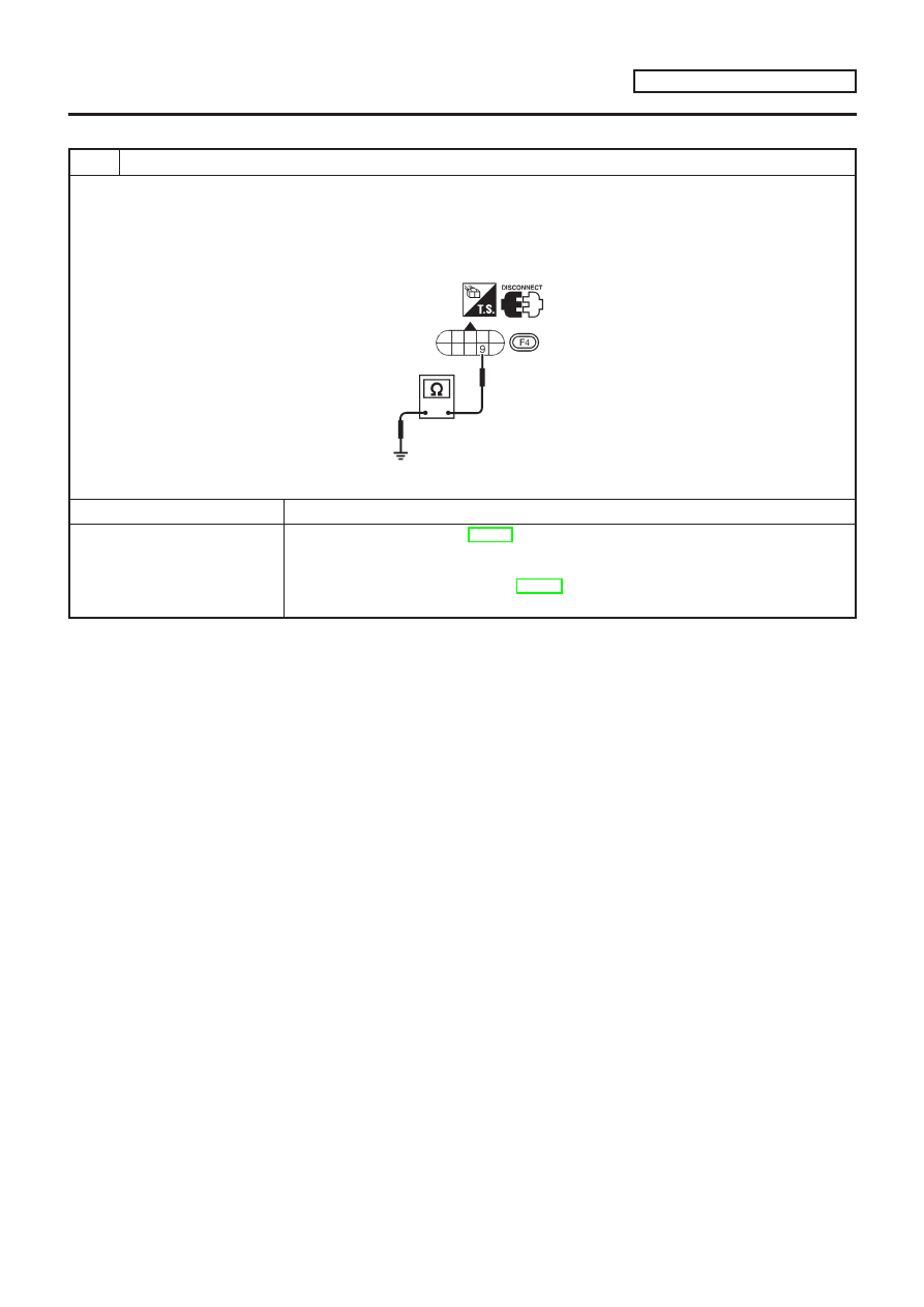
CHECK VALVE RESISTANCE

1. Turn ignition switch to “OFF” position.
2. Disconnect terminal cord assembly connector in engine compartment.
3. Check resistance between terminal 9 and ground.

Resistance:

10 - 20

SAT269K

OK or NG

OK

©

GO TO 2.

NG

©

1. Remove oil pan. Refer to AT-206.
2. Check the following items:

+

Torque converter clutch solenoid valve
Refer to “Component Inspection”, AT-169.

+

Harness of terminal cord assembly for short or open

TORQUE CONVERTER CLUTCH

SOLENOID VALVE

EXCEPT FOR EURO-OBD

Diagnostic Procedure

AT-167

2

CHECK POWER SOURCE CIRCUIT

1. Turn ignition switch to “OFF” position.
2. Disconnect TCM harness connector.
3. Check continuity between terminal 5 and TCM harness connector terminal 3.

Continuity should exist.

SAT683JA

If OK, check harness for short to ground and short to power.

4. Reinstall any part removed.

OK or NG

OK

©

GO TO 3.

NG

©

Repair open circuit or short to ground or short to power in harness or connectors.

3

CHECK DTC

Perform Self-diagnosis Code confirmation procedure, AT-165.

OK or NG

OK

©

INSPECTION END

NG

©

1. Perform TCM input/output signal inspection.
2. If NG, recheck TCM pin terminals for damage or loose connection with harness con-

nector.

TORQUE CONVERTER CLUTCH

SOLENOID VALVE

EXCEPT FOR EURO-OBD

Diagnostic Procedure (Cont’d)

AT-168

SAT684JA

Component Inspection

NLAT0280

TORQUE CONVERTER CLUTCH SOLENOID VALVE

NLAT0280S01

+

For removal, refer to AT-206.

Resistance Check

NLAT0280S0101

+

Check resistance between two terminals.

Solenoid valve

Terminal No.

Resistance

(Approx.)

Torque converter
clutch solenoid
valve

9

Ground

10 - 20

SAT685JA

Operation Check

NLAT0280S0102

+

Check solenoid valve by listening for its operating sound while
applying battery voltage to the terminal and ground.

TORQUE CONVERTER CLUTCH

SOLENOID VALVE

EXCEPT FOR EURO-OBD

Component Inspection

AT-169

SAT021J

Description

NLAT0281

The CVT fluid temperature sensor detects the CVT fluid tempera-
ture and sends a signal to the TCM.

CONSULT-II REFERENCE VALUE IN DATA MONITOR
MODE

NLAT0281S01

Remarks: Specification data are reference values.

Monitor item

Condition

Specification (Approximately)

CVT temperature sensor

Cold [20°C (68°F)]

Hot [80°C (176°F)]

1.5V

0.5V

2.5 k

0.3 k

TCM TERMINALS AND REFERENCE VALUE

NLAT0281S02

Remarks: Specification data are reference values.

Terminal

No.

Wire color

Item

Condition

Judgement stan-

dard (Approx.)

42

B

Ground
(CVT fluid tem-
perature sensor)

47

BR

CVT fluid tem-
perature sensor

When ATF temperature is 20°C
(68°F).

1.5V

When ATF temperature is 80°C
(176°F).

0.5V

ON BOARD DIAGNOSIS LOGIC

NLAT0281S03

Diagnostic trouble code

Malfunction is detected when ...

Check items (Possible cause)

: FLUID TEMP SEN

TCM receives an excessively low or high
voltage from the sensor.

+

Harness or connectors
(The sensor circuit is open or shorted.)

+

CVT fluid temperature sensor

: 8th judgement flicker

CVT FLUID TEMPERATURE

SENSOR CIRCUIT

EXCEPT FOR EURO-OBD

Description

AT-170

SAT250K

SAT821HB

SELF-DIAGNOSIS CODE CONFIRMATION PROCEDURE

NLAT0281S04

After the repair, perform the following procedure to confirm the
malfunction is eliminated.

With CONSULT-II

NLAT0281S0401

1)

Start engine.

2)

Select “SELF-DIAG RESULTS” mode for CVT with CONSULT-
II.

3)

Drive vehicle under the following conditions:
Selector lever in “D” position, vehicle speed higher than 10
km/h (6 MPH), throttle opening greater than 1/8 of the full open
position, engine speed higher than 450 rpm and driving for
more than 10 minutes.

Without CONSULT-II

NLAT0281S0402

1)

Start engine.

2)

Drive vehicle under the following conditions:
Selector lever in “D” position, vehicle speed higher than 10
km/h (6 MPH), throttle opening greater than 1/8 of the full open
position, engine speed higher than 450 rpm and driving for
more than 10 minutes.

3)

Perform self-diagnosis.
Refer

to

“SELF-DIAGNOSTIC

PROCEDURE

(Without

CONSULT-II)”, AT-35.

CVT FLUID TEMPERATURE

SENSOR CIRCUIT

EXCEPT FOR EURO-OBD

Description (Cont’d)

AT-171

Wiring Diagram — AT — FTS

NLAT0282

MODELS WITH ECM IN ENGINE COMPARTMENT

NLAT0282S01

YAT175

CVT FLUID TEMPERATURE

SENSOR CIRCUIT

EXCEPT FOR EURO-OBD

Wiring Diagram — AT — FTS

AT-172

MODELS WITH ECM IN CABIN

NLAT0282S02

YAT214

CVT FLUID TEMPERATURE

SENSOR CIRCUIT

EXCEPT FOR EURO-OBD

Wiring Diagram — AT — FTS (Cont’d)

AT-173

Diagnostic Procedure

NLAT0283

1

CHECK A/T FLUID TEMPERATURE SENSOR WITH TERMINAL CORD ASSEMBLY

1. Turn ignition switch to “OFF” position.
2. Disconnect terminal cord assembly connector in engine compartment.
3. Check resistance between terminals 6 and 7 when CVT is cold.

Resistance:

Cold [20°C (68°F)]

Approximately 2.5 k

SAT229K

4. Reinstall any part removed.

OK or NG

OK (With CONSULT-II)

©

GO TO 2.

OK (Without CONSULT-
II)

©

GO TO 3.

NG

©

Replace CVT assembly.

2

CHECK INPUT SIGNAL OF A/T FLUID TEMPERATURE SENSOR (WITH CONSULT-II)

With CONSULT-II

1. Start engine.
2. Select “TCM INPUT SIGNALS” in “DATA MONITOR” mode for “CVT” with CONSULT-II.
3. Read out the value of “FLUID TEMP SE”.

Voltage:

Cold [20°C (68°F)]

Hot [80°C (176°F)]:

Approximately 1.5V

0.5V

SAT271K

OK or NG

OK

©

GO TO 4.

NG

©

Check the following item:

+

Harness for short or open between TCM, ECM and terminal cord assembly (Main har-
ness)

+

Ground circuit for ECM
Refer to EC section, “TROUBLE DIAGNOSIS FOR POWER SUPPLY”.

CVT FLUID TEMPERATURE

SENSOR CIRCUIT

EXCEPT FOR EURO-OBD

Diagnostic Procedure

AT-174

3

CHECK INPUT SIGNAL OF CVT FLUID TEMPERATURE SENSOR (WITHOUT CONSULT-II)

Without CONSULT-II

1. Start engine.
2. Check voltage between TCM terminal 47 and ground while warming up CVT.

Voltage:

Cold [20°C (68°F)]

Hot [80°C (176°F)]:

Approximately 1.5V

0.5V

SAT463J

3. Turn ignition switch to “OFF” position.
4. Disconnect TCM harness connector.
5. Check resistance between terminal 42 and ground.

Continuity should exist.

SAT464J

OK or NG

OK

©

GO TO 4.

NG

©

Check the following item:

+

Harness for short or open between TCM, ECM and terminal cord assembly (Main har-
ness)

+

Ground circuit for ECM
Refer to EC section, “TROUBLE DIAGNOSIS FOR POWER SUPPLY”.

4

CHECK DTC

Perform Self-diagnosis Code confirmation procedure, AT-171.

OK or NG

OK

©

INSPECTION END

NG

©

1. Perform TCM input/output signal inspection.
2. If NG, recheck TCM pin terminals for damage or loose connection with harness con-

nector.

CVT FLUID TEMPERATURE

SENSOR CIRCUIT

EXCEPT FOR EURO-OBD

Diagnostic Procedure (Cont’d)

AT-175

Description

NLAT0285

The engine speed signal is sent from the ECM to the TCM.

TCM TERMINALS AND REFERENCE VALUE

NLAT0285S01

Remarks: Specification data are reference values.

Terminal

No.

Wire color

Item

Condition

Judgement stan-

dard (Approx.)

39

L/OR

Engine speed
signal

When engine runs at idle speed.

0.5 - 1.5V

ON BOARD DIAGNOSIS LOGIC

NLAT0285S02

Diagnostic trouble code

Malfunction is detected when ...

Check item (Possible cause)

: ENGINE SPEED SIG

TCM does not receive the proper voltage
signal from ECM.

+

Harness or connectors
(The sensor circuit is open or shorted.)

: 9th judgement flicker

SAT250K

SAT823H

SELF-DIAGNOSIS CODE CONFIRMATION PROCEDURE

NLAT0285S03

After the repair, perform the following procedure to confirm the
malfunction is eliminated.

With CONSULT-II

NLAT0285S0301

1)

Start engine.

2)

Select “SELF-DIAG RESULTS” mode for CVT with CONSULT-
II.

3)

Drive vehicle under the following conditions:
Selector lever in “D” position, vehicle speed higher than 10
km/h (6 MPH), throttle opening greater than 1/8 of the full
throttle position and driving for more than 10 seconds.

Without CONSULT-II

NLAT0285S0302

1)

Start engine.

2)

Drive vehicle under the following conditions:
Selector lever in “D” position, vehicle speed higher than 10
km/h (6 MPH), throttle opening greater than 1/8 of the full
throttle position and driving for more than 10 seconds.

3)

Perform self-diagnosis.
Refer

to

“SELF-DIAGNOSTIC

PROCEDURE

(Without

CONSULT-II)”, AT-35.

ENGINE SPEED SIGNAL

EXCEPT FOR EURO-OBD

Description

AT-176

Wiring Diagram — AT — ENGSS

NLAT0286

YAT178

ENGINE SPEED SIGNAL

EXCEPT FOR EURO-OBD

Wiring Diagram — AT — ENGSS

AT-177

Diagnostic Procedure

NLAT0287

1

CHECK DTC WITH ECM

Perform diagnostic test mode II (self-diagnostic results) for engine control. Check ignition signal circuit condition.

OK or NG

OK (With CONSULT-II)

©

GO TO 2.

OK (Without CONSULT-
II)

©

GO TO 3.

NG

©

Check ignition signal circuit for engine control. Refer to EC section, “IGNITION SIGNAL”.

2

CHECK INPUT SIGNAL (With CONSULT-II)

With CONSULT-II

1. Start engine.
2. Select “TCM INPUT SIGNALS” in “DATA MONITOR” mode for “CVT” with CONSULT-II.

SAT250K

3. Read out the value of “ENGINE SPEED”.

Check engine speed changes according to throttle position.

SAT271K

OK or NG

OK

©

GO TO 4.

NG

©

Check the following items:

+

Harness for short or open between TCM and ECM

+

Resistor and ignition coil
Refer to EC section, “IGNITION SIGNAL”.

ENGINE SPEED SIGNAL

EXCEPT FOR EURO-OBD

Diagnostic Procedure

AT-178

3

CHECK INPUT SIGNAL (Without CONSULT-II)

Without CONSULT-II

1. Start engine.
2. Check voltage between TCM terminal 39 and ground.

Voltage (Idle speed):

Refer to EC section, “IGNITION SIGNAL”.

SAT424JA

OK or NG

OK

©

GO TO 4.

NG

©

Check the following items:

+

Harness for short or open between TCM and ECM

+

Resistor and ignition coil
Refer to EC section, “IGNITION SIGNAL”.

4

CHECK DTC

Perform Self-diagnosis Code confirmation procedure, AT-176.

OK or NG

OK

©

INSPECTION END

NG

©

1. Perform TCM input/output signal inspection.
2. If NG, recheck TCM pin terminals for damage or loose connection with harness con-

nector.

ENGINE SPEED SIGNAL

EXCEPT FOR EURO-OBD

Diagnostic Procedure (Cont’d)

AT-179

SAT574J

Description

NLAT0288

The TCM consists of a microcomputer and connectors for signal
input and output and for power supply. The unit controls the CVT.

ON BOARD DIAGNOSIS LOGIC

NLAT0288S01

Diagnostic trouble code

Malfunction is detected when ...

Check item (Possible cause)

: CONTROL UNIT (RAM)
: CONTROL UNIT (ROM)

TCM memory (RAM) or (ROM) is mal-
functioning.

TCM

SAT250K

SAT252K

DIAGNOSTIC TROUBLE CODE (DTC) CONFIRMATION
PROCEDURE

NLAT0288S02

NOTE:
If “DIAGNOSTIC TROUBLE CODE CONFIRMATION PROCE-
DURE” has been previously conducted, always turn ignition
switch “OFF” and wait at least 5 seconds before conducting
the next test.

With CONSULT-II

1)

Turn ignition switch “ON” and select “DATA MONITOR” mode
for CVT with CONSULT-II.

2)

Start engine.

3)

Run engine for at least 2 seconds at idle speed.

CONTROL UNIT (RAM), CONTROL UNIT (ROM)

Description

AT-180

Diagnostic Procedure

=NLAT0289

1

CHECK DTC

With CONSULT-II

1. Turn ignition switch “ON” and select “SELF-DIAG RESULTS” mode for CVT with CONSULT-II.
2. Touch “ERASE”.
PERFORM DIAGNOSTIC TROUBLE CODE (DTC) CONFIRMATION PROCEDURE.
See previous page.

Is the “CONTROL UNIT (RAM) or CONTROL UNIT (ROM)” displayed again?

Yes

©

Replace TCM.

No

©

INSPECTION END

CONTROL UNIT (RAM), CONTROL UNIT (ROM)

Diagnostic Procedure

AT-181

SAT574J

Description

NLAT0241

The TCM consists of a microcomputer and connectors for signal
input and output and for power supply. The unit controls the CVT.

ON BOARD DIAGNOSIS LOGIC

NLAT0241S01

Diagnostic trouble code

Malfunction is detected when ...

Check item (Possible cause)

: CONT UNIT (EEPROM)

TCM memory (EEPROM) is malfunction-
ing.

TCM

SAT250K

SAT252K

DIAGNOSTIC TROUBLE CODE (DTC) CONFIRMATION
PROCEDURE

NLAT0241S02

NOTE:
If “DIAGNOSTIC TROUBLE CODE CONFIRMATION PROCE-
DURE” has been previously conducted, always turn ignition
switch “OFF” and wait at least 5 seconds before conducting
the next test.

With CONSULT-II

1)

Turn ignition switch “ON” and select “DATA MONITOR” mode
for CVT with CONSULT-II.

2)

Start engine.

3)

Run engine for at least 2 seconds at idle speed.

CONTROL UNIT (EEPROM)

Description

AT-182


Content      ..     11      12      13      14     ..