Nissan Almera Tino V10. Manual - part 185
AT-464
[ALL]
REPAIR FOR COMPONENT PARTS
3.
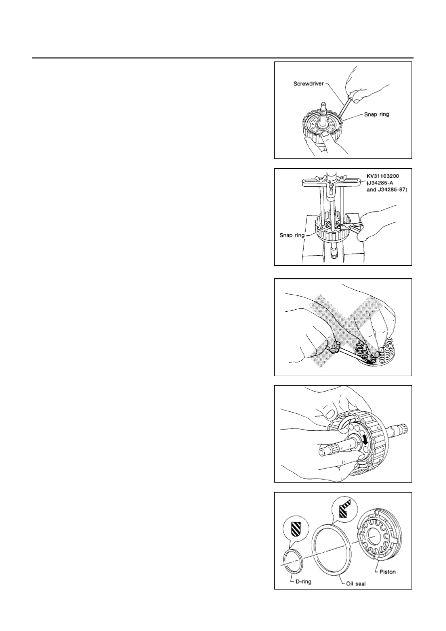
Remove snap ring.
4.
Remove drive plates, driven plates and retaining plate.
5.
Set Tool on spring retainer and remove snap ring from high
clutch drum while compressing return springs.
●
Set Tool directly over springs.
●
Do not expand snap ring excessively.
6.
Remove spring retainer and return springs.
●
Do not remove return spring from spring retainer.
7.
Remove piston from high clutch drum by turning it.
8.
Remove D-ring and oil seal from piston.
SAT178D
AAT683
SAT302E
SAT189D
SAT139E