Nissan Pathfinder (2011 year). Manual - part 228


  Index      Manuals     Nissan Pathfinder (2011 year) - Service and Repair Manual


Search            copyright infringement  


Content      ..     226      227      228      229     ..


Nissan Pathfinder (2011 year). Manual - part 228


DLN-362

< UNIT DISASSEMBLY AND ASSEMBLY >

[FRONT FINAL DRIVE: R180A]

FRONT FINAL DRIVE

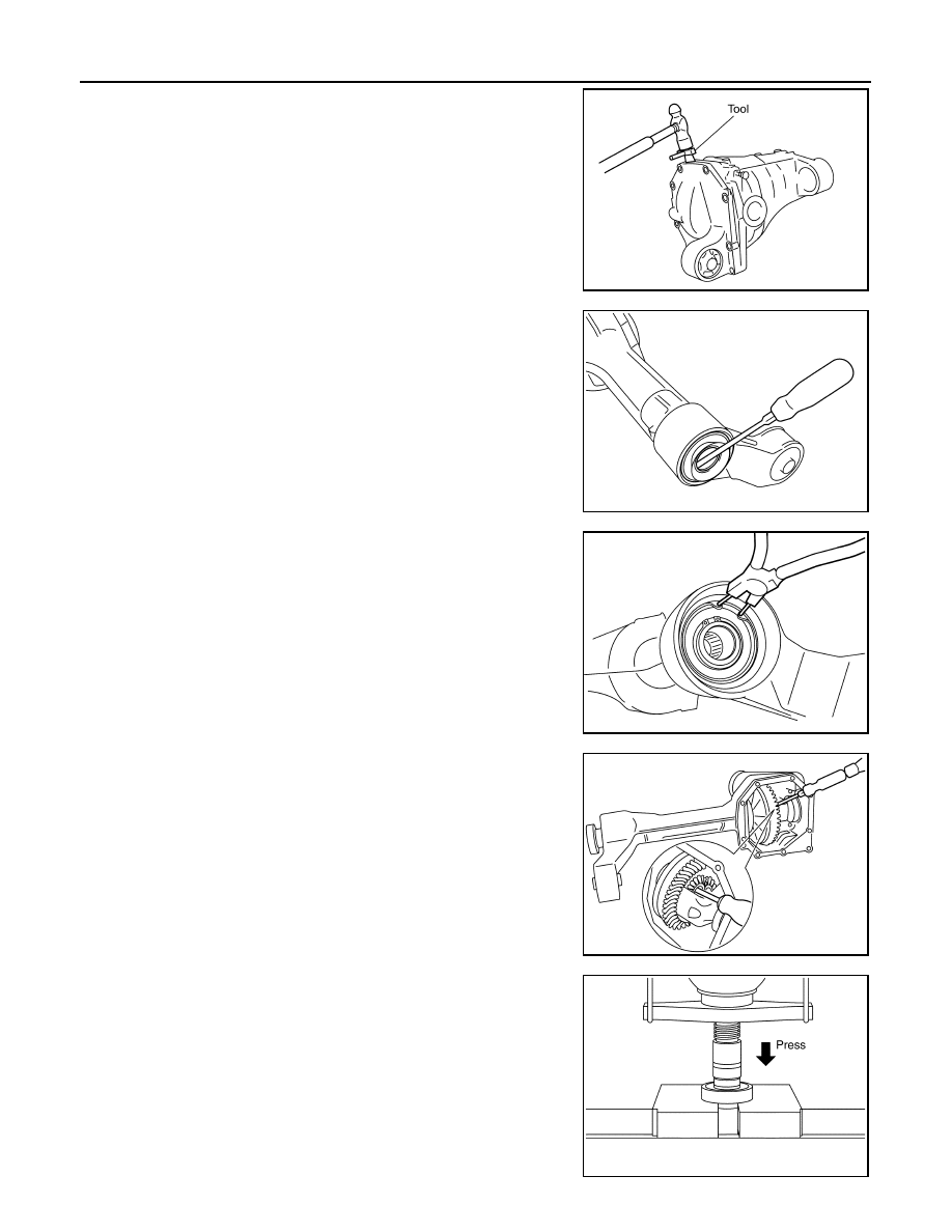
2. Remove the carrier cover bolts and separate the carrier cover

from the gear carrier using Tool.

CAUTION:

• Do not damage the mating surface.

• Do not insert flat-bladed screwdriver, this will damage the

mating surface.

3. Remove side oil seal, using suitable tool.

CAUTION:

Do not damage gear carrier.

4. Remove snap ring (hole side) using suitable tool.

5. Remove differential side shaft assembly out of gear carrier using

suitable tool.

NOTE:

Tap on differential side shaft assembly from side gear side.

6. Remove snap ring (differential side shaft side).

7. Press differential side shaft out of differential side shaft bearing.

CAUTION:

Do not drop differential side shaft.

Tool number

: KV10111100 (J-37228)

PDIA0699E

PDIA0713E

PDIA0714E

PDIA0715E

PDIA0718E

2011 Pathfinder

FRONT FINAL DRIVE

DLN-363

< UNIT DISASSEMBLY AND ASSEMBLY >

[FRONT FINAL DRIVE: R180A]

C

E

F

G

H

I

J

K

L

M

A

B

DLN

N

O

P

Differential Assembly

1. Remove differential side shaft assembly. Refer to 

DLN-354, "Removal and Installation"

.

2. Remove side seal from gear carrier using suitable tool.
3. For proper reinstallation, paint matching marks on one side of

the side bearing cap and gear carrier.

CAUTION:

• For matching marks, use paint. Do not damage side bear-

ing cap or gear carrier.

• Side bearing caps are line-board during manufacture. The

matching marks are used to reinstall them in their original

positions.

4. Remove the side bearing caps.

5. Lift the differential case assembly out of the gear carrier.

CAUTION:

• Keep side bearing outer races together with side bearing

inner races. Do not mix them up.

• Keep side bearing adjusting washers together with side

bearings.

6. Remove housing spacer.
7. Remove side bearing inner race using Tools as shown.

CAUTION:

• Do not remove side bearing inner race unless it is being

replaced.

• Place copper plates between the vise and the side bearing

inner race and drive gear to prevent damage.

PDIA0700E

PDIA0701E

SPD919

Tool number

 A: ST33051001 (J-22888-20)
 B: ST33061000 (J-8107-2)

PDIA0827E

2011 Pathfinder

DLN-364

< UNIT DISASSEMBLY AND ASSEMBLY >

[FRONT FINAL DRIVE: R180A]

FRONT FINAL DRIVE

• Keep side bearing outer races together with side bearing

inner races. Do not mix them up.

8. For proper reinstallation, paint matching marks on the differential

case and drive gear.

CAUTION:

Use paint for matching marks. Do not damage differential

case or drive gear.

9. Remove the drive gear bolts.
10. Tap the drive gear off the differential case using suitable tool.

CAUTION:

Tap evenly all around to keep drive gear from bending.

11. Remove the lock pin of the pinion mate shaft from the drive gear

side using suitable tool.

12. Remove the pinion mate shaft.

13. Turn the pinion mate gear, then remove the pinion mate gear,

pinion mate thrust washer, side gear and side gear thrust

washer from the differential case.

SPD022

PDIA0496E

SPD025

SDIA0031J

SDIA0032J

2011 Pathfinder

FRONT FINAL DRIVE

DLN-365

< UNIT DISASSEMBLY AND ASSEMBLY >

[FRONT FINAL DRIVE: R180A]

C

E

F

G

H

I

J

K

L

M

A

B

DLN

N

O

P

Drive Pinion Assembly

1. Remove the differential assembly.
2. Remove the drive pinion lock nut using suitable tool.
3. Put matching marks on the companion flange and drive pinion

using paint.

CAUTION:

Use paint to make the matching marks. Do not damage the

companion flange or drive pinion.

4. Remove the companion flange using suitable tool.

5. Press the drive pinion assembly (with rear inner bearing race

and collapsible spacer) out of the gear carrier.

CAUTION:

Do not drop drive pinion assembly.

6. Remove the drive pinion rear bearing inner race and drive pinion

height adjusting washer using Tool.

PDIA0702E

PDIA0703E

PDIA0704E

Tool number

: ST30031000 (J-22912-01)

S-PD179

2011 Pathfinder

DLN-366

< UNIT DISASSEMBLY AND ASSEMBLY >

[FRONT FINAL DRIVE: R180A]

FRONT FINAL DRIVE

7. Remove the front oil seal using suitable tool.

CAUTION:

Do not damage gear carrier.

8. Remove the drive pinion front bearing inner race.
9. Remove the drive pinion front and rear bearing outer races by

tapping them uniformly using suitable tool.

CAUTION:

Do not damage gear carrier.

INSPECTION AFTER DISASSEMBLY

Clean the disassembled parts. Then inspect the parts for wear or damage. If wear or damage are found, follow

the measures below.

Drive Pinion and Drive Gear

• If the drive pinion and drive gear teeth do not mesh or line-up correctly, determine the cause and adjust,

repair, or replace as necessary.

• If the drive pinion or drive gear are worn, cracked, damaged, pitted or chipped (by friction) noticeably,

replace with new drive pinion and drive gear.

• Drive pinion and drive gear are supplied in matched sets only. Matching numbers on both drive pinion and

drive gear are etched for verification. If a new drive pinion and drive gear set are being used, verify the num-

bers of each drive pinion and drive gear before proceeding with assembly.

Bearing

• If bearings are chipped (by friction), pitted, worn, rusted, scratched, or unusual noise is coming from bearing,

replace with new bearing assembly (as a new set).

• Bearing must be replaced with a new one whenever disassembled.

Side Gear and Pinion Mate Gear

• If any cracks or damage are found on the surface of the teeth, replace with new one.

• If any worn or chipped marks are found on the side of the side gear and pinion mate gear which contact the

thrust washer, replace with new one.

• Replace both side gear and pinion mate gear as a set when replacing side gear or pinion mate gear.

Side Gear Thrust Washer and Pinion Mate Thrust Washer

• If any chips (by friction), damage, or unusual wear are found, replace with new one.

Gear Carrier

• If any wear or cracks are found on the contact sides of gear carrier, replace with new one.

Companion Flange

• If any chips (about 0.1mm, 0.004 in) or other damage on the companion flange surface which contacts the

front oil seal lips are found, replace with new one.

ADJUSTING AND SELECTING WASHERS

Side Gear Back Clearance

• Assemble the differential parts if they are disassembled. Refer to 

DLN-358, "Exploded View"

.

PDIA0716E

PDIA0705E

2011 Pathfinder

FRONT FINAL DRIVE

DLN-367

< UNIT DISASSEMBLY AND ASSEMBLY >

[FRONT FINAL DRIVE: R180A]

C

E

F

G

H

I

J

K

L

M

A

B

DLN

N

O

P

1. Place the differential case straight up so that the side gear to be

measured is upward.

2. Using feeler gauges, measure the clearance between the side

gear back and differential case at three different points, while

rotating the side gear. Average the three readings to calculate

the clearance. (Measure the clearance of the other side as well.)

• If the side gear back clearance is outside of the specification,

use a thicker or thinner side gear thrust washer to adjust.

Refer to 

DLN-377, "Inspection and Adjustment"

.

CAUTION:

• Insert feeler gauges with the same thickness on both

sides to prevent side gear from tilting.

• Each gear should rotate smoothly without excessive

resistance during differential motion.

• Select a side gear thrust washer for right and left individually.

NOTE:

Side gear back clearance is clearance between side gear and differential case for adjusting side gear

backlash.

Drive Pinion Height

1. Make sure all parts are clean and that the bearings are well lubricated.
2. Assemble the drive pinion bearings onto the Tool.

PDIA0460E

Side gear back clearance: Refer to 

DLN-377, "Inspec-

tion and Adjustment"

If the side gear back clearance is greater than 
specification:

Use a thicker side gear thrust washer.

If the side gear back clearance is less than spec-
ification:

Use a thinner side gear thrust washer.

PDIA0576E

Tool number

 (J-34309)

SPD769

2011 Pathfinder

DLN-368

< UNIT DISASSEMBLY AND ASSEMBLY >

[FRONT FINAL DRIVE: R180A]

FRONT FINAL DRIVE

Drive pinion front bearing;

 make sure the J-34309-3 drive

pinion front bearing seat is secured tightly against the J-

34309-2 gauge anvil. Then turn the J-34309-7 drive pinion

front bearing pilot to secure the drive pinon front bearing in its

proper position.

Drive pinion rear bearing;

 the J-34309-8 drive pinion rear

bearing pilot is used to center the drive pinion rear bearing

only. The J-34309-4 drive pinion rear bearing locking seat is

used to lock the drive pinion rear bearing to the assembly.

Installation of J-34309-9 and J-34309-16;

 place a suitable

2.5 mm (0.098 in) thick plain washer between J-34309-9 and

J-34309-16. Both surfaces of J-34309-9 and J-34309-16 must

be parallel with a clearance of 2.5 mm (0.098 in).

3. Install the drive pinion rear bearing inner race into the gear car-

rier. Then insert the drive pinion height adjusting washer selec-

tor tool, J-34309-1, gauge screw assembly.

4. Assemble the drive pinion front bearing inner race and the J-

34309-2 gauge anvil. Assemble them together with the J-34309-

1 gauge screw in the gear carrier. Make sure that the drive pin-

ion height gauge plate, J-34309-16, will turn a full 360

°

. Tighten

the two sections together by hand.

5. Turn the assembly several times to seat the drive pinon bear-

ings.

SPD197A

SPD893

SPD199A

SPD770

2011 Pathfinder

FRONT FINAL DRIVE

DLN-369

< UNIT DISASSEMBLY AND ASSEMBLY >

[FRONT FINAL DRIVE: R180A]

C

E

F

G

H

I

J

K

L

M

A

B

DLN

N

O

P

6. Measure the turning torque at the end of the J-34309-2 gauge

anvil using Tool.

7. Place the J-34309-10 “R180A” drive pinion height adapter onto

the gauge plate and tighten it by hand.

CAUTION:

Make sure all machined surfaces are clean.

8. Position the side bearing discs, Tool, and arbor firmly into the

side bearing bores. Install the side bearing caps and tighten the

side bearing cap bolts to the specified torque. Refer to 

DLN-358,

"Exploded View"

.

9. Select the correct standard drive pinion height adjusting washer

thickness. Select by using a standard gauge of 3 mm (0.12 in)

and your J-34309-101 feeler gauge. Measure the distance

between the J-34309-10 drive pinion height adapter, including

the standard gauge and the arbor.

10. Write down the exact measurement (the value of feeler gauge).

Tool number

: ST3127S000 (J-25765- A)

Turning torque specification:

1.0 - 1.6 N·m (0.11 - 0.16 kg-m, 9 - 14 in-lb)

PDIA0566E

SPD208A

Tool number

 (J-25269-18)

SPD211A

SPD204A

SPD775

2011 Pathfinder


Content      ..     226      227      228      229     ..