Nissan Pathfinder (2009 year). Manual - part 492


  Index      Manuals     Nissan Pathfinder (2009 year) - Service and Repair Manual


Search            copyright infringement  


Content      ..     490      491      492      493     ..


Nissan Pathfinder (2009 year). Manual - part 492


LAN-22

< BASIC INSPECTION >

[CAN FUNDAMENTAL]

DIAGNOSIS AND REPAIR WORKFLOW

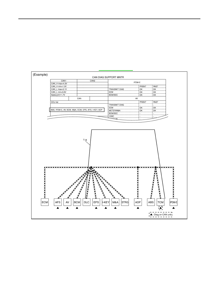
Identify the error circuit using information from the “CAN DIAG SUPPORT MNTR” (“ECU list” included).

1.

ECU list: Check the items indicated in “ECU list”. Draw a line on the diagnosis sheet to indicate the error
circuit.
NOTE:
CAN communication line has no error if units other than Diag on CAN units are not indicated. An error
may be on the power supply of the control unit, DDL1 line or DDL2 line.

a.

“TCM” which is Diag on CAN unit, is not indicated on “ECU list”. This indicates that DLC is not receiving a
signal from TCM. Draw a line to indicate an error between DLC and TCM (line 1-a in the figure below).
NOTE:
• Diag on CAN units are not indicated on the “ECU list” when the CAN line between Diag on CAN unit and

the data link connector is open.

• For a description of Diag on CAN, refer to 

LAN-6, "Description"

.

2.

CAN DIAG SUPPORT MNTR: Check each item on “CAN DIAG SUPPORT MNTR”. Draw a line on the
diagnosis sheet to indicate the error circuit.

a.

Reception item of “ECM”: On “TCM”, “UNKWN” is indicated. This means ECM cannot receive the signal
from TCM. Draw a line to indicate an error between ECM and TCM (line 2-a in the figure below).
NOTE:
If “UNKWN” is indicated on “TRANSMIT DIAG”, then the control unit cannot transmit CAN communication
signal to each unit. Draw a line between the control unit and the splice.

b.

Reception item of “AFS”: On “TCM”, “UNKWN” is indicated. This means AFS cannot receive the signal
from TCM. Draw a line to indicate an error between AFS and TCM (line 2-b in the figure below).

PKID1214E

2009 Pathfinder

LAN

DIAGNOSIS AND REPAIR WORKFLOW

LAN-23

< BASIC INSPECTION >

[CAN FUNDAMENTAL]

C

D

E

F

G

H

I

J

K

L

B

A

O

P

N

c.

Reception item of “AV”: “UNKWN” is not indicated. This indicates normal communication between AV and
its receiving units. Do not draw any line.

d.

Reception item of “BCM”: On “TCM”, “UNKWN” is indicated. This means BCM cannot receive the signal
from TCM. Draw a line to indicate an error between BCM and TCM (line 2-d in the figure below).

e.

Reception item of “EPS” and “I-KEY”: “UNKWN” is not indicated. This indicates normal communication
between EPS and I-KEY and their receiving units. Do not draw any line.
NOTE:

PKID1215E

2009 Pathfinder

LAN-24

< BASIC INSPECTION >

[CAN FUNDAMENTAL]

DIAGNOSIS AND REPAIR WORKFLOW

On CAN DIAG SUPPORT MNTR (without PAST), “UNKWN” is indicated even though the item is not used
in the trouble diagnosis. For the details of each item on CAN diagnostic support monitor, refer to 

LAN-61,

"CAN Diagnostic Support Monitor"

.

f.

Reception item of “M&A”: On “TCM”, “UNKWN” is indicated. This means M&A cannot receive the signal
from TCM. Draw a line to indicate an error between M&A and TCM (line 2-f in the figure below).

g.

Reception item of “ADP”: On “TCM”, “UNKWN” is indicated. This means ADP cannot receive the signal
from TCM. Draw a line to indicate an error between ADP and TCM (line 2-g in the figure below).

PKID1216E

2009 Pathfinder

LAN

DIAGNOSIS AND REPAIR WORKFLOW

LAN-25

< BASIC INSPECTION >

[CAN FUNDAMENTAL]

C

D

E

F

G

H

I

J

K

L

B

A

O

P

N

h.

Reception item of “ABS”: “UNKWN” is not indicated. This indicates normal communication between ABS
and its receiving units. Do not draw any line.

i.

Reception item of “IPDM-E”: “UNKWN” is not indicated. This indicates normal communication between
IPDM-E and its receiving units. Do not draw any line.

3.

Based on information received from “CAN DIAG SUPPORT MNTR”, place a check mark on the known
good CAN communication line between ECM and IPDM-E.

a.

Through the previous procedure, the circuit between ADP splice and TCM has the most amount of lines
(shade 3-a in the figure below).

b.

Place a check mark on the known good lines to establish the error circuit.

PKID1217E

2009 Pathfinder

LAN-26

< BASIC INSPECTION >

[CAN FUNDAMENTAL]

DIAGNOSIS AND REPAIR WORKFLOW

Reception item of “IPDM-E”: On “ECM”, “OK” is indicated. IPDM-E communicates normally with ECM. Put
a check mark on the normal circuit between ECM and IPDM-E (check mark 3-b in the figure below).

4.

Through the above procedure, the error is detected in the TCM branch line (shaded in the figure below).
NOTE:
For abbreviations, refer to 

LAN-36, "Abbreviation List"

.

PKID1218E

2009 Pathfinder

LAN

DIAGNOSIS AND REPAIR WORKFLOW

LAN-27

< BASIC INSPECTION >

[CAN FUNDAMENTAL]

C

D

E

F

G

H

I

J

K

L

B

A

O

P

N

5.

Perform the inspection for the detected error circuit. For the inspection procedure, refer to “MALFUNC-
TION AREA CHART”. 

Present Error — Short Circuit —

When the symptoms listed below exist, a short circuit of the CAN communication line is a possible cause.

Received data

Error symptom

• Most the units connected to the CAN communication system go into fail-safe mode or are deactivated.

Inspection procedure

PKID1219E

Item (CONSULT-III)

Indication

ECU list (on the CAN DIAG SUPPORT MNTR)

All Diag on CAN units are not indicated.

CAN DIAG SUPPORT MNTR

“UNKWN” is indicated under “TRANSMIT DIAG” and most reception items.

2009 Pathfinder

LAN-28

< BASIC INSPECTION >

[CAN FUNDAMENTAL]

DIAGNOSIS AND REPAIR WORKFLOW

• Refer to “MALFUNCTION AREA CHART”.

Past Error — Open Circuit —

Review CAN communication signal chart based on information received from the interview with the customer
and on past error information from SELF-DIAG RESULTS and CAN DIAG SUPPORT MNTR.

PKID1220E

2009 Pathfinder

LAN

DIAGNOSIS AND REPAIR WORKFLOW

LAN-29

< BASIC INSPECTION >

[CAN FUNDAMENTAL]

C

D

E

F

G

H

I

J

K

L

B

A

O

P

N

1.

SELF-DIAG RESULTS: Inspect the control units indicating “U1000” or “U1001” on SELF-DIAG RESULTS.

2.

CAN DIAG SUPPORT MNTR (with PAST): Check the CAN DIAG SUPPORT MNTR (with PAST) of units
indicating “U1000” or “U1001” on SELF-DIAG RESULTS. Draw a line on the diagnosis sheet to indicate
the possible error circuit.
NOTE:
For the details of each indication on CAN DIAG SUPPORT MNTR, refer to 

LAN-61, "CAN Diagnostic Sup-

port Monitor"

.

a.

Reception item of “ECM”: “VDC/TCS/ABS”, “3” is indicated in the “PAST”. This means ECM could not
receive the signal from ABS in the past. Draw a line between ECM and ABS (line 2-a in the figure below).

b.

Reception item of “M&A”: “VDC/TCS/ABS”, “3” is indicated in the “PAST”. This means M&A could not
receive the signal from ABS in the past. Draw a line between M&A and ABS (line 2-b in the figure below).

PKID1221E

2009 Pathfinder


Content      ..     490      491      492      493     ..