Nissan Pathfinder (2008 year). Manual - part 616


  Index      Manuals     Nissan Pathfinder (2008 year) - Service and Repair Manual


Search            copyright infringement  


Content      ..     614      615      616      617     ..


Nissan Pathfinder (2008 year). Manual - part 616


TM-270

< DISASSEMBLY AND ASSEMBLY >

DISASSEMBLY

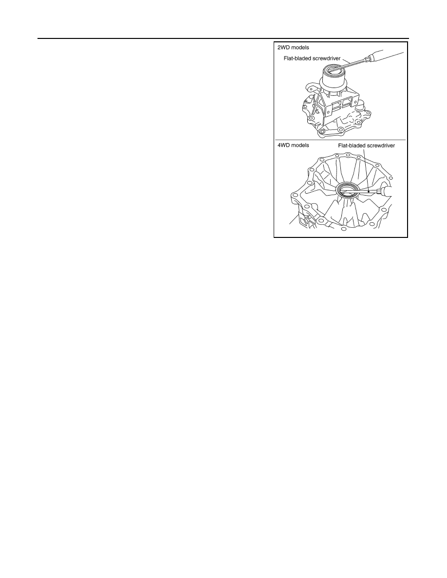
75. Remove rear oil seal from rear extension (2WD models) or

adapter case (4WD models) using suitable tool.

CAUTION:

Do not scratch rear extension (2WD models) or adapter
case (4WD models).

SCIA5272E

OIL PUMP

TM-271

< DISASSEMBLY AND ASSEMBLY >

C

E

F

G

H

I

J

K

L

M

A

B

TM

N

O

P

OIL PUMP

Exploded View

INFOID:0000000001726725

Oil Pump

Disassembly and Assembly

INFOID:0000000001726731

DISASSEMBLY

1.

Remove oil pump housing from oil pump cover.

2.

Remove oil pump housing oil seal using suitable tool.

CAUTION:

Do not scratch oil pump housing.

1.

O-ring

2.

Oil pump cover

3.

O-ring

4.

Oil pump housing

5.

Oil pump housing oil seal

SCIA5227E

SCIA5228E

SCIA2840E

TM-272

< DISASSEMBLY AND ASSEMBLY >

OIL PUMP

3.

Remove O-ring from oil pump housing.

4.

Remove O-ring from oil pump cover.

ASSEMBLY

1.

Install O-ring to oil pump cover.

CAUTION:

• Do not reuse O-ring.
• Apply ATF to O-ring.

2.

Install O-ring to oil pump housing.

CAUTION:

• Do not reuse O-ring.
• Apply ATF to O-ring.

SCIA2841E

SCIA5230E

SCIA5230E

SCIA2841E

OIL PUMP

TM-273

< DISASSEMBLY AND ASSEMBLY >

C

E

F

G

H

I

J

K

L

M

A

B

TM

N

O

P

3.

Install oil pump housing oil seal to the oil pump housing until it is
flush using Tool.

CAUTION:

• Do not reuse oil seal.
• Apply ATF to oil seal.

4.

After temporarily tightening the bolts for the oil pump housing to
the oil pump cover, tighten them to the specified torque in the
sequence shown.

Tool number

: ST33400001 (J-26082)

SCIA5313E

Oil pump housing bolts

: 9.0 N·m (0.92 kg-m, 80 in-lb.)

SCIA6329E

TM-274

< DISASSEMBLY AND ASSEMBLY >

FRONT SUN GEAR, 3RD ONE-WAY CLUTCH

FRONT SUN GEAR, 3RD ONE-WAY CLUTCH

Exploded View

INFOID:0000000001726726

Disassembly and Assembly

INFOID:0000000001726737

DISASSEMBLY

1.

Remove snap ring from front sun gear using suitable tool.

2.

Remove 3rd one-way clutch from front sun gear.

INSPECTION

3rd One-way Clutch

• Check frictional surface for wear or damage.

CAUTION:

If necessary, replace the 3rd one-way clutch.

1.

Front sun gear

2.

3rd one-way clutch

3.

Snap ring

SCIA3114E

SCIA3110E

SCIA3111E

FRONT SUN GEAR, 3RD ONE-WAY CLUTCH

TM-275

< DISASSEMBLY AND ASSEMBLY >

C

E

F

G

H

I

J

K

L

M

A

B

TM

N

O

P

Front Sun Gear Snap Ring

• Check for deformation, fatigue or damage.

CAUTION:

If necessary, replace the snap ring.

Front Sun Gear

• Check for deformation, fatigue or damage.

CAUTION:

If necessary, replace the front sun gear.

ASSEMBLY

1.

Install 3rd one-way clutch in front sun gear.

CAUTION:

Apply ATF to 3rd one-way clutch.

2.

Install snap ring in front sun gear using suitable tool.

3.

Check operation of 3rd one-way clutch.

a.

Hold oil pump assembly and turn front sun gear.

b.

Check 3rd one-way clutch for correct locking and unlocking
directions.

CAUTION:

If not as shown, check installation direction of 3rd one-way
clutch.

SCIA3111E

SCIA3110E

SCIA3131E

TM-276

< DISASSEMBLY AND ASSEMBLY >

FRONT CARRIER, INPUT CLUTCH, REAR INTERNAL GEAR

FRONT CARRIER, INPUT CLUTCH, REAR INTERNAL GEAR

Exploded View

INFOID:0000000001726727

Disassembly and Assembly

INFOID:0000000001726746

DISASSEMBLY

1.

Seal ring

2.

O-ring

3.

Needle bearing

4.

Bearing race

5.

Front carrier assembly

6.

Needle bearing

7.

Snap ring

8.

Snap ring

9.

Retaining plate

10. Driven plate

11.

Input clutch drum

12. Drive plate

13. Rear internal gear

SCIA6734E

FRONT CARRIER, INPUT CLUTCH, REAR INTERNAL GEAR

TM-277

< DISASSEMBLY AND ASSEMBLY >

C

E

F

G

H

I

J

K

L

M

A

B

TM

N

O

P

1.

Compress snap ring using 2 flat-bladed screwdrivers.

2.

Remove front carrier assembly and input clutch assembly from
rear internal gear.

3.

Remove front carrier assembly from input clutch assembly.

a.

Remove bearing race from front carrier assembly.

b.

Remove needle bearing from front carrier assembly.

c.

Remove snap ring from front carrier assembly.

CAUTION:

Do not excessively expand snap ring.

4.

Disassemble input clutch assembly.

a.

Remove O-ring and seal rings from input clutch assembly.

SCIA5339E

SCIA2847E

SCIA5233E

SCIA5476E

SCIA5235E


Content      ..     614      615      616      617     ..