Index Manuals Nissan Pathfinder (2008 year) - Service and Repair Manual
Search copyright infringement
Content .. 595 596 597 598 ..
Nissan Pathfinder (2008 year). Manual - part 597
TM-118
< ECU DIAGNOSIS >
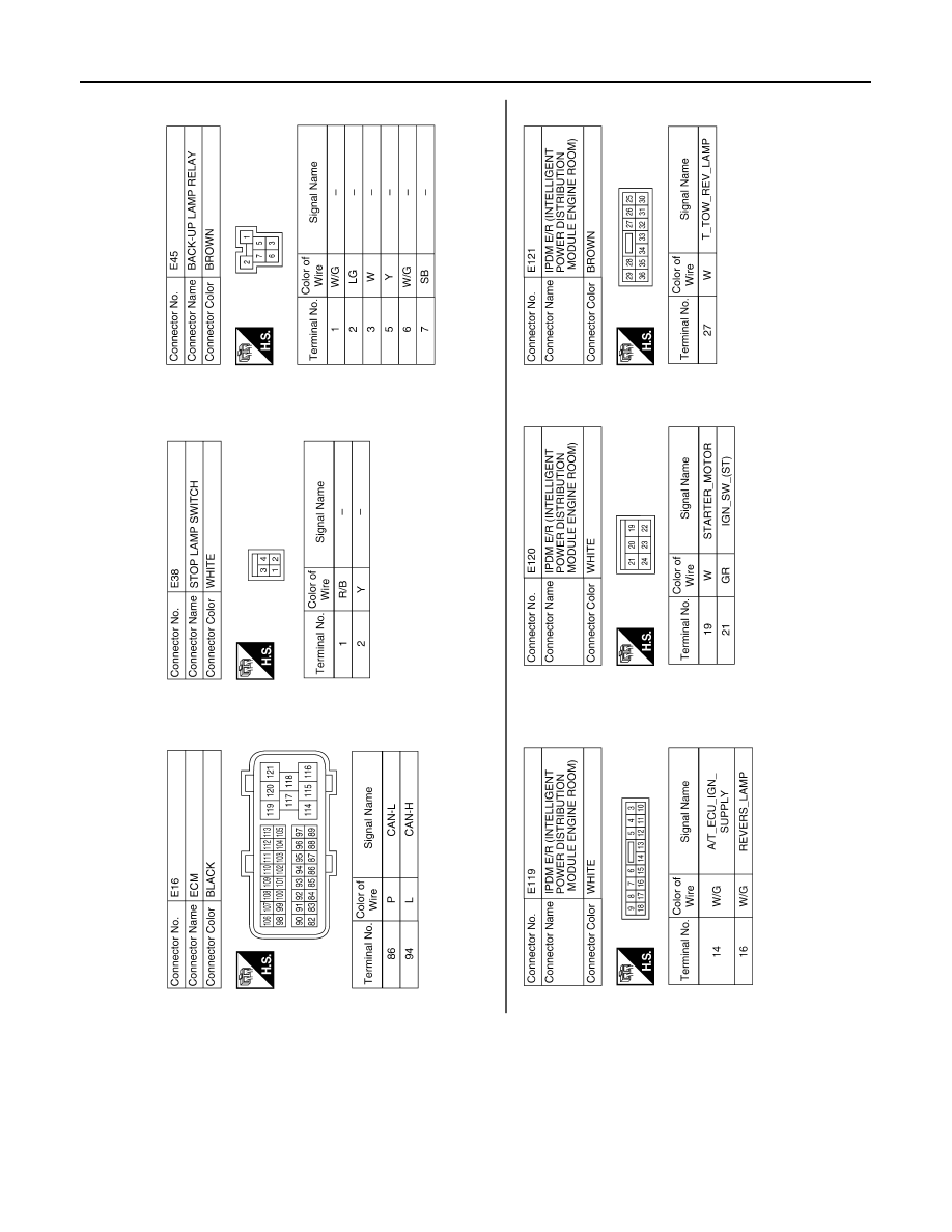
TCM
ALDIA0075GB