Nissan Pathfinder (2008 year). Manual - part 595
TM-102
< COMPONENT DIAGNOSIS >
MAIN POWER SUPPLY AND GROUND CIRCUIT
3.
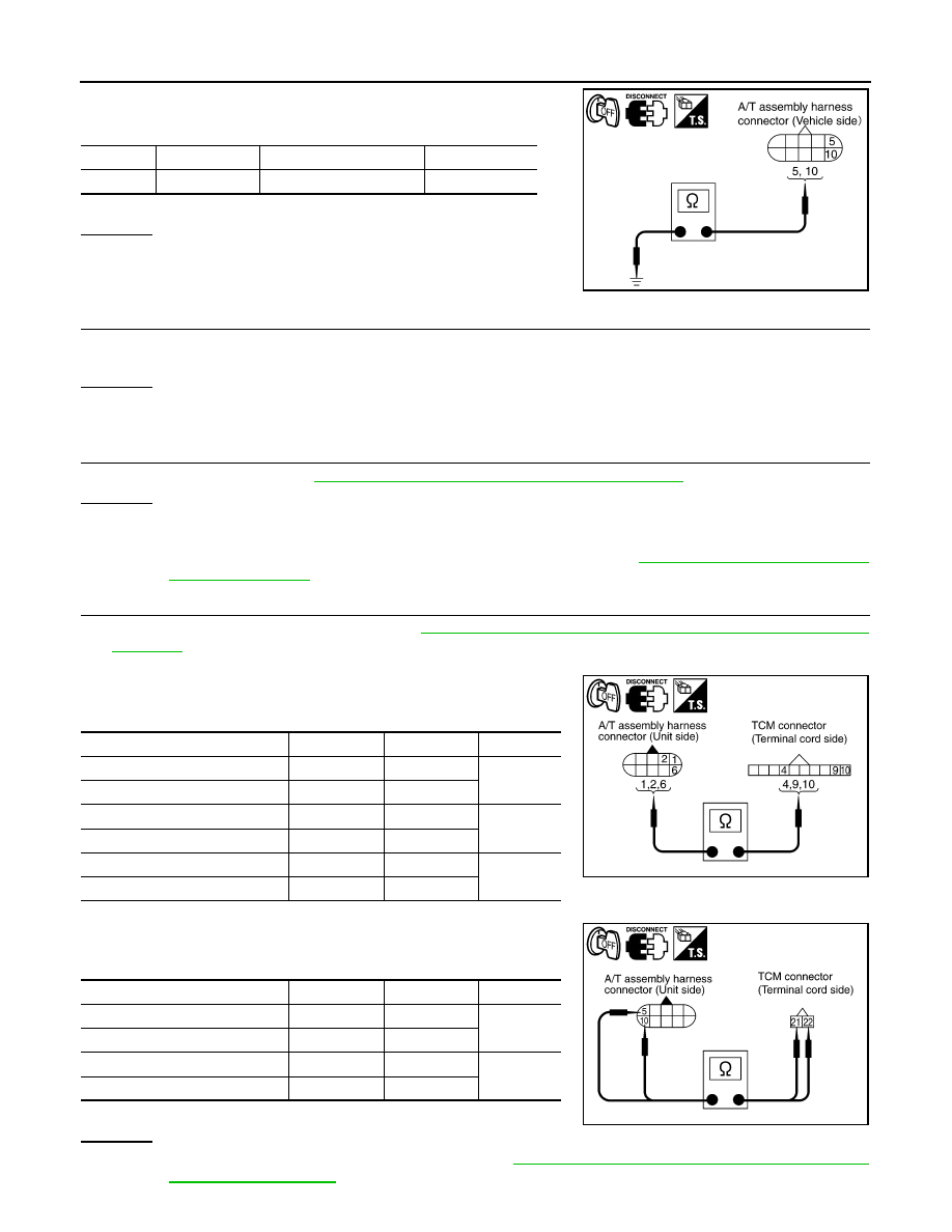
Check continuity between A/T assembly harness connector ter-
minals and ground.
If OK, check harness for short to ground and short to power.
OK or NG
OK
>> GO TO 5.
NG
>> Repair open circuit or short to ground or short to power
in harness or connectors.
5.
DETECT MALFUNCTIONING ITEM
Check the following.
• The A/T assembly harness connector terminals for damage or loose connection with harness connector.
OK or NG
OK
>> GO TO 6.
NG
>> Repair or replace damaged parts.
6.
PERFORM SELF-DIAGNOSIS
Perform self-diagnosis. Refer to
TM-35, "CONSULT-III Function (TRANSMISSION)"
OK or NG
OK
>> INSPECTION END
NG-1
>> Self-diagnosis does not activate: GO TO 7.
NG-2
>> DTC is displayed: Check the malfunctioning system. Refer to
7.
CHECK TERMINAL CORD ASSEMBLY
1.
Remove control valve with TCM. Refer to
TM-199, "Control Valve with TCM and A/T Fluid Temperature
.
2.
Disconnect A/T assembly harness connector and TCM connector.
3.
Check continuity between A/T assembly harness connector ter-
minals and TCM connector terminals.
4.
Check continuity between A/T assembly harness connector ter-
minals and TCM connector terminals.
5.
If OK, check harness for short to ground and short to power.
OK or NG
OK
>> Replace the control valve with TCM. Refer to
TM-199, "Control Valve with TCM and A/T Fluid
.
Item
Connector
Terminal
Continuity
TCM
F9
5, 10 - Ground
Yes
SCIA2106E
Item
Connector
Terminal
Voltage
A/T assembly harness connector
F9
1
Yes
TCM connector
F502
9
A/T assembly harness connector
F9
2
Yes
TCM connector
F502
10
A/T assembly harness connector
F9
6
Yes
TCM connector
F502
4
SCIA5464E
Item
Connector
Terminal
Voltage
A/T assembly harness connector
F9
5
Yes
TCM connector
F504
21
A/T assembly harness connector
F9
10
Yes
TCM connector
F504
22
SCIA5465E