Nissan Pathfinder (2008 year). Manual - part 548
VEHICLE SECURITY SYSTEM
SEC-17
< FUNCTION DIAGNOSIS >
[WITH INTELLIGENT KEY SYSTEM]
C
D
E
F
G
H
I
J
L
M
A
B
SEC
N
O
P
VEHICLE SECURITY SYSTEM
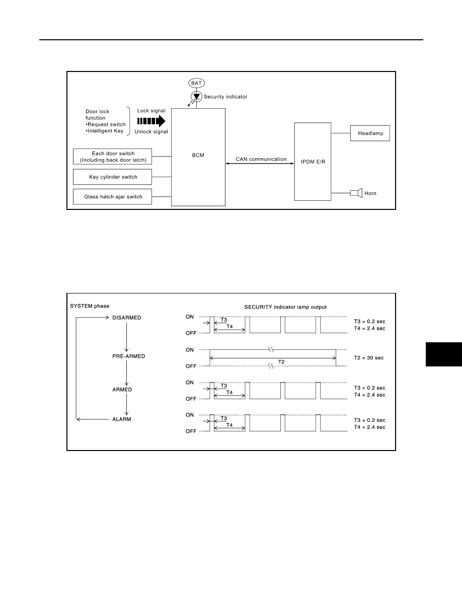
System Diagram
INFOID:0000000001689517
System Description
INFOID:0000000001689518
DESCRIPTION
The security system provides an audible and visual alarm when an unauthorized access to the vehicle is
detected while the system is in armed phase.
The security system consist of the BCM managing the audible alarm (horn) and the visual alarm (headlamps).
OPERATION FLOW
Disarmed Phase
When the vehicle is being driven or when doors are open, the theft warning system is set in the disarmed
phase on the assumption that the owner is inside or near the vehicle.
Pre-Armed Phase And Armed Phase
The vehicle security system turns into the pre-armed phase when ignition switch is in OFF position, all doors
are closed and locked (using Intelligent Key, door request switch or auto relock function). The system auto-
matically shifts into the armed phase.
Condition of Activating The System
When the following condition is performed in armed phase, the system sounds the horns and flashes the
headlamps for about 30 seconds.
• Any door is opened.
ALKIA0709GB
PIIA1367E