Nissan Pathfinder (2008 year). Manual - part 468
IP-16
< DISASSEMBLY AND ASSEMBLY >
CENTER CONSOLE ASSEMBLY
Assembly
Assembly is in the reverse order of disassembly.
Center Console
Disassembly
1.
Remove center console. Refer to
IP-10, "Removal and Installation"
2.
Remove center console lid.
3.
Remove latch from center console lid.
4.
Remove hinge from center console lid.
5.
Remove rear finisher assembly.
6.
Remove rear cup holder assembly.
7.
Remove DVD player, if equipped.
8.
Disconnect center console harness connectors.
9.
Remove cup holder insert and cup holder assembly.
10. Remove center console bin.
11. Remove center console bracket.
12. Remove wire harness bracket.
Assembly
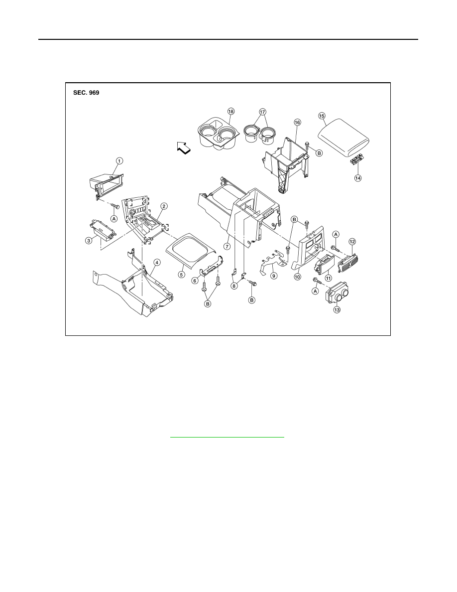
AWJIA0058ZZ
1.
Console bin
2.
A/T finisher
3.
Ash tray
4.
Center console front base
5.
Cup holder finisher
6.
Bracket
7.
Center console rear base
8.
Bracket DVD
9.
Wire harness bracket
10.
Rear finisher assembly
11.
Rear cup holder assembly
12.
Ventilator console grille (if equipped)
13.
Rear HVAC control (if equipped)
14.
Hinge
15.
Center console lid
16.
Center console bin
17.
Cup holder insert
18.
Cup holder assembly
A.
Screw
B.
Bolt