Nissan Pathfinder (2008 year). Manual - part 430
COMPRESSOR
HA-43
< ON-VEHICLE REPAIR >
C
D
E
F
G
H
J
K
L
M
A
B
HA
N
O
P
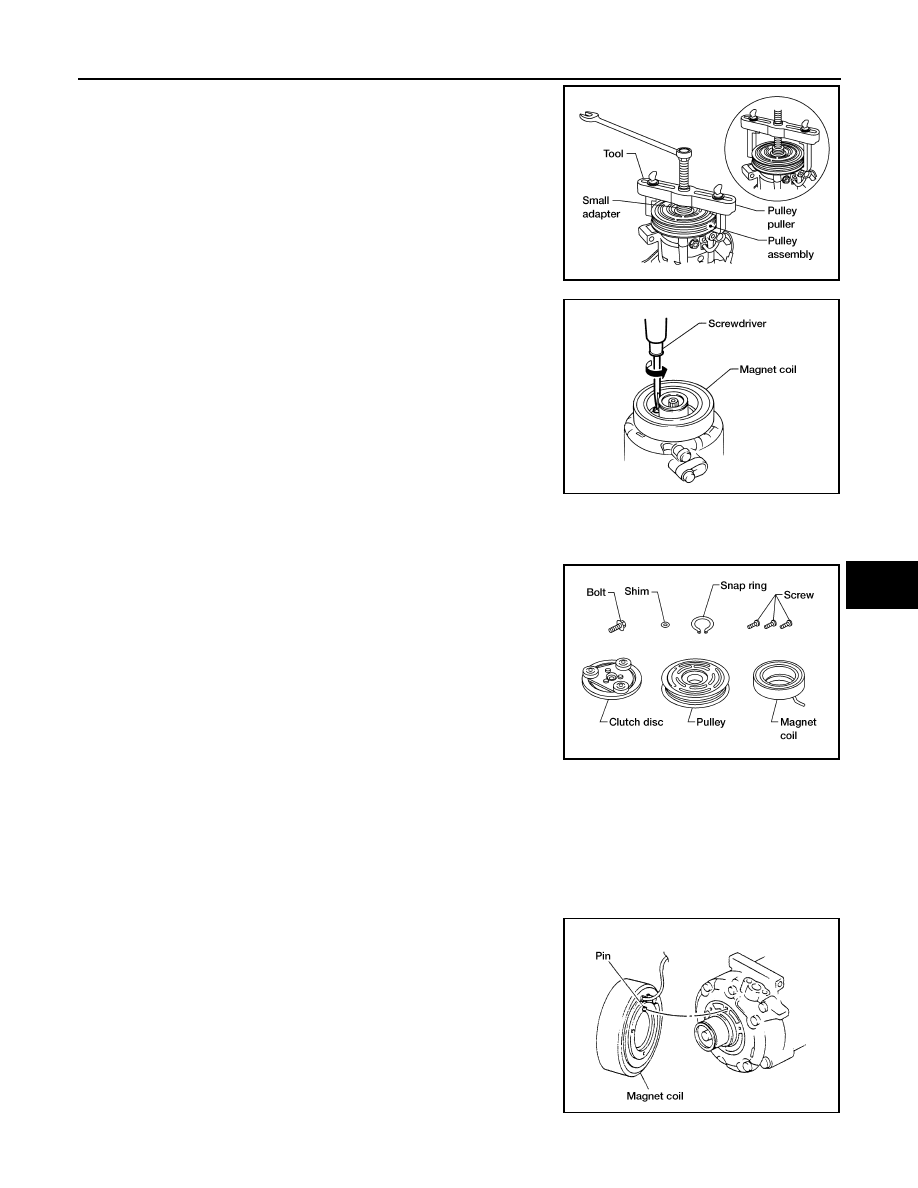
5.
Remove the pulley using Tool with a small adapter. Position the
small adapter on the end of the drive shaft and the center of the
puller on the small adapter.
CAUTION:
To prevent deformation of the pulley groove, the puller
claws should be hooked under the pulley groove and not
into the pulley groove.
6.
Remove the magnet coil harness clip using a screwdriver,
remove the three magnet coil fixing screws and remove the
magnet coil.
INSPECTION
Clutch Disc
If the contact surface shows signs of damage due to excessive heat,
replace clutch disc and pulley.
Pulley
Check the appearance of the pulley assembly. If contact surface of pulley shows signs of excessive grooving,
replace clutch disc and pulley. The contact surfaces of the pulley assembly should be cleaned with a suitable
solvent before reinstallation.
Coil
Check magnet coil for loose connections or any cracked insulation.
INSTALLATION
1.
Install the magnet coil.
CAUTION:
Be sure to align the magnet coil pin with the hole in the
compressor front head.
2.
Install the magnet coil harness clip using a screwdriver.
Tool number
: KV99233130 (J-29884)
WJIA1017E
WHA212
WHA183
WHA213