Index Manuals Nissan Pathfinder (2008 year) - Service and Repair Manual
Search copyright infringement
Content .. 398 399 400 401 ..
Nissan Pathfinder (2008 year). Manual - part 400
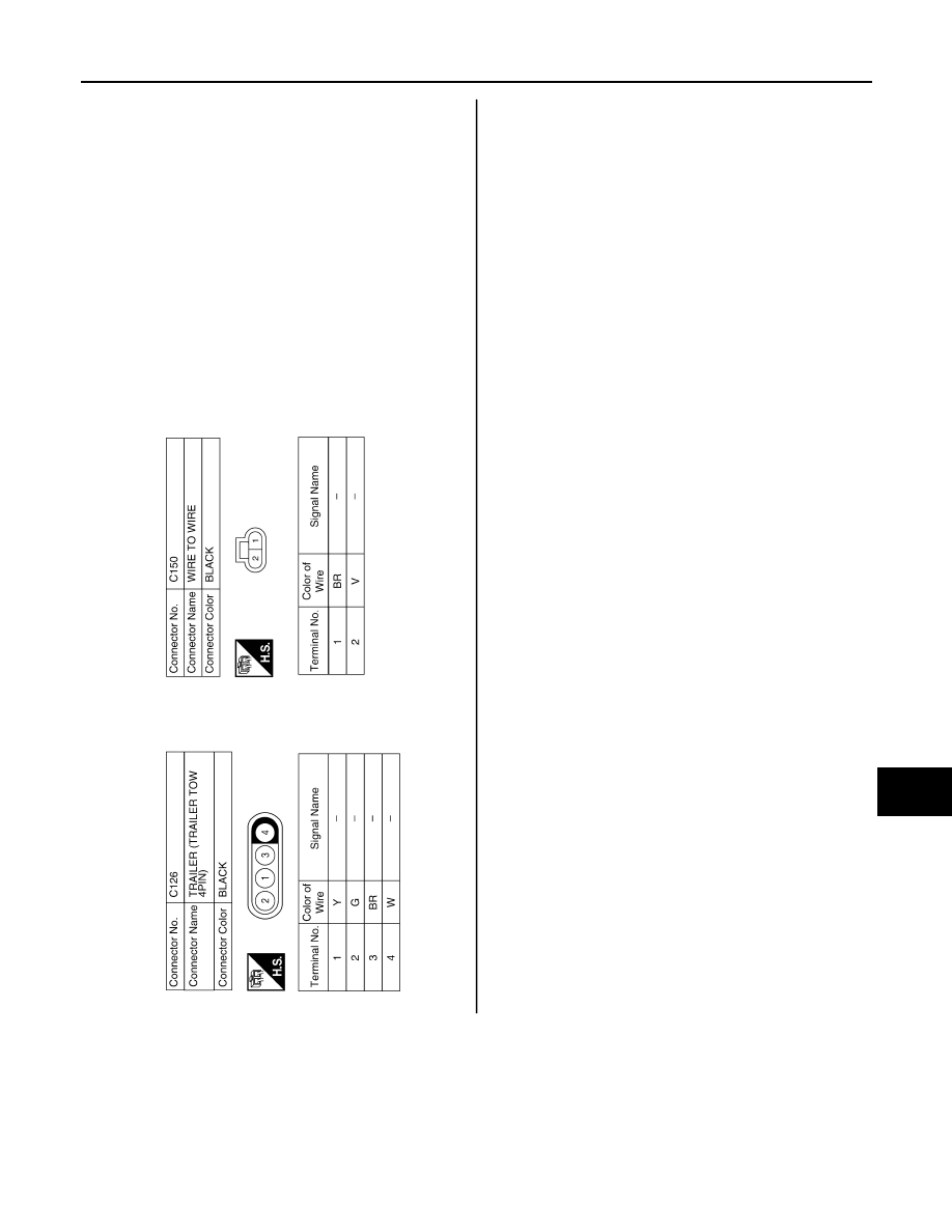
TRAILER TOW
EXL-99
< COMPONENT DIAGNOSIS >
C
D
E
F
G
H
I
J
K
M
A
B
EXL
N
O
P
ALLIA0499GB