Nissan Pathfinder (2008 year). Manual - part 374
AIR CLEANER FILTER
EM-155
< ON-VEHICLE MAINTENANCE >
[VK56DE]
C
D
E
F
G
H
I
J
K
L
M
A
EM
N
P
O
AIR CLEANER FILTER
Removal and Installation
INFOID:0000000001468877
REMOVAL
NOTE:
• The viscous paper type filter does not need cleaning between replacement intervals.
• Replace the air filter as necessary for periodic maintenance. Refer to
MA-6, "Introduction of Periodic Mainte-
.
1.
Unhook clips, and lift air cleaner case (upper).
2.
Remove the air cleaner filter.
INSTALLATION
1.
Installation is in the reverse order of removal.
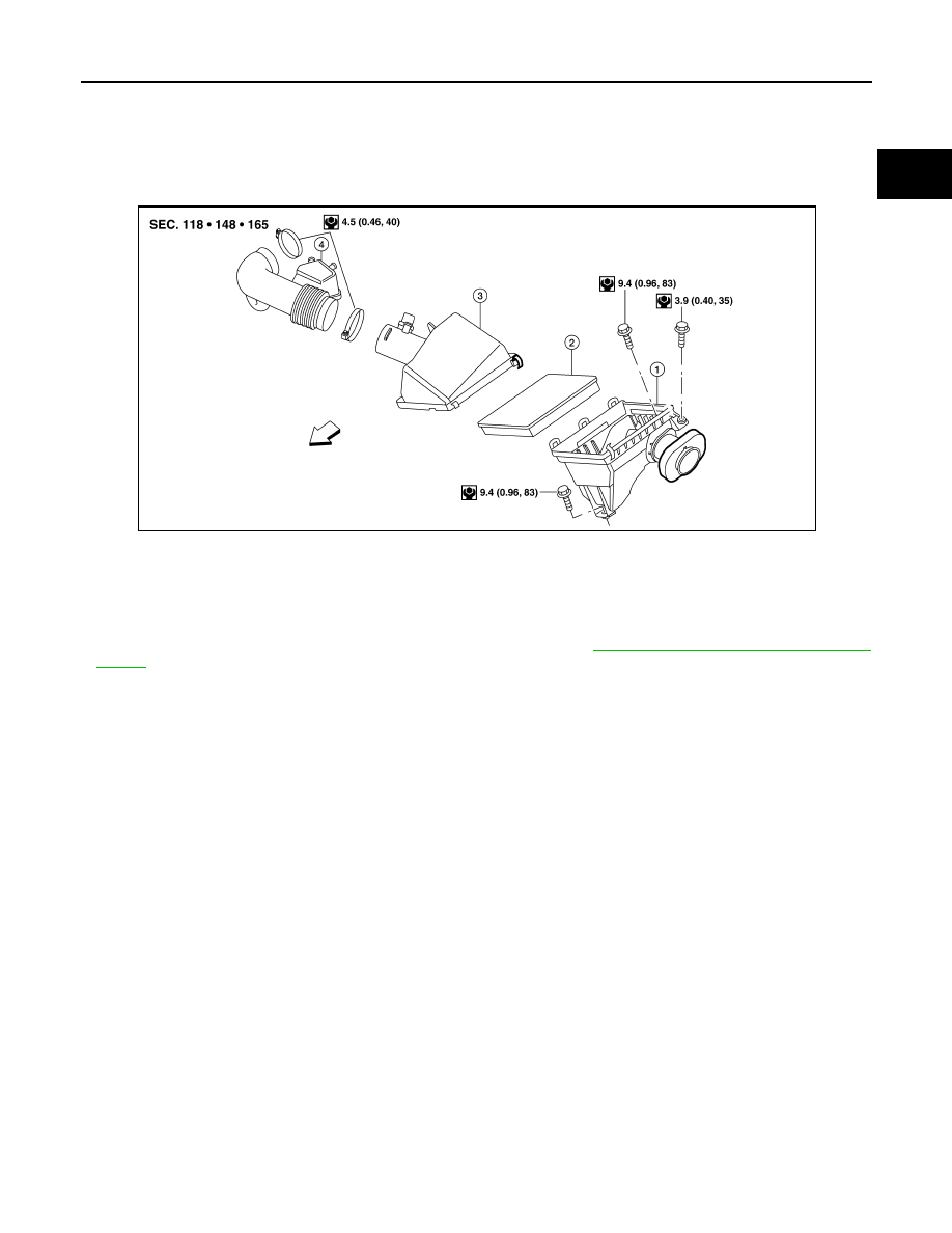
1.
Air cleaner case (lower)
2.
Air cleaner filter
3.
Air cleaner case (upper)
4.
Air duct and resonator assembly
⇐
Front
ALBIA0413GB