Nissan Pathfinder (2008 year). Manual - part 372
SERVICE DATA AND SPECIFICATIONS (SDS)
EM-139
< SERVICE DATA AND SPECIFICATIONS (SDS)
[VQ40DE]
C
D
E
F
G
H
I
J
K
L
M
A
EM
N
P
O
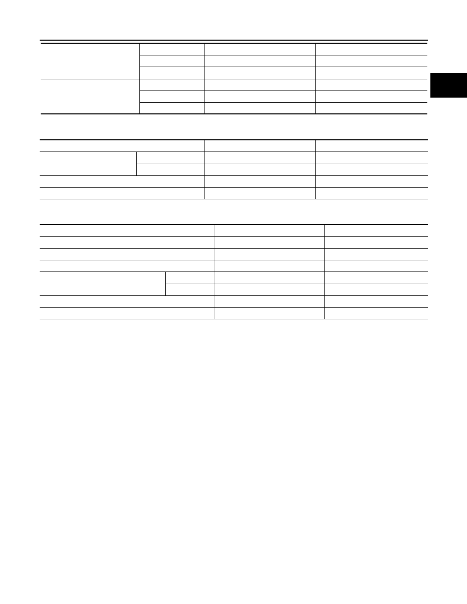
Piston Pin
Unit: mm (in)
CONNECTING ROD
Unit: mm (in)
*: After installing in connecting rod
CRANKSHAFT
Side clearance
Top
0.045 - 0.080 (0.0018 - 0.0031)
0.11 (0.0043)
2nd
0.030 - 0.070 (0.0012 - 0.0028)
0.10 (0.0039)
Oil ring
0.065 - 0.135 (0.0026 - 0.0053)
—
End gap
Top
0.23 - 0.33 (0.0091 - 0.0130)
0.56 (0.0220)
2nd
0.33 - 0.48 (0.0130 - 0.0189)
0.68 (0.0268)
Oil (rail ring)
0.20 - 0.50 (0.0079 - 0.0197)
0.85 (0.0335)
Items
Standard
Limit
Piston pin outer diameter
Grade No. 0
21.989 - 21.995 (0.8657 - 0.8659)
—
Grade No. 1
21.995 - 22.001 (0.8659 - 0.8662)
—
Piston to piston pin oil clearance
0.002 - 0.006 (0.0001 - 0.0002)
—
Connecting rod bushing oil clearance
0.005 - 0.017 (0.0002 - 0.0007)
0.030 (0.0012)
Items
Standard
Limit
Center distance
165.82 - 165.92 (6.5283 - 6.5323)
—
Bend [per 100 (3.94)]
—
0.15 (0.0059)
Torsion [per 100 (3.94)]
—
0.30 (0.0118)
Connecting rod bushing inner diameter*
Grade No. 0
22.000 - 22.006 (0.8661 - 0.8664)
—
Grade No. 1
22.006 - 22.012 (0.8664 - 0.8666)
—
Connecting rod big end diameter (Without bearing)
57.000 - 57.013 (2.2441 - 2.2446)
—
Side clearance
0.20 - 0.35 (0.0079 - 0.0138)
: 40 mm (0.0157)