Nissan Pathfinder (2008 year). Manual - part 366
OIL SEAL
EM-91
< ON-VEHICLE REPAIR >
[VQ40DE]
C
D
E
F
G
H
I
J
K
L
M
A
EM
N
P
O
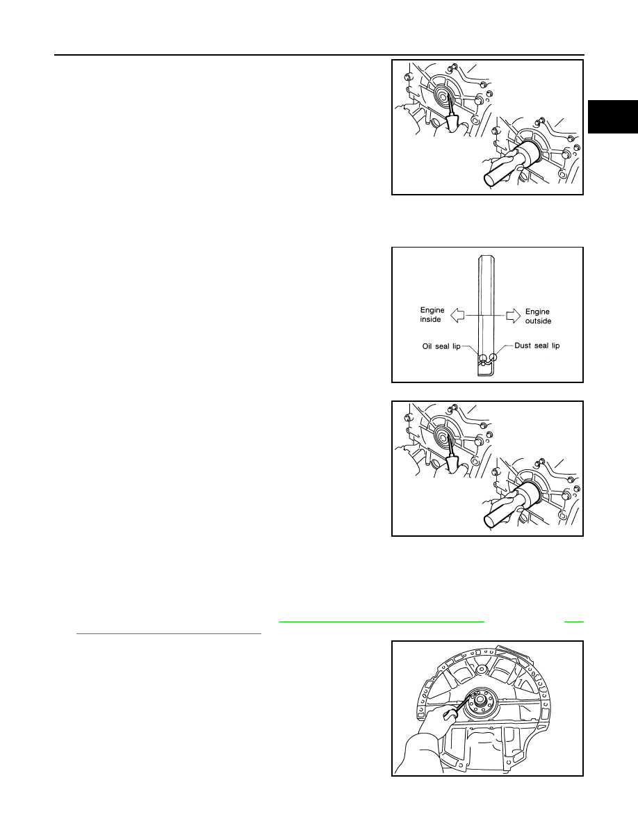
5.
Remove front oil seal using suitable tool.
CAUTION:
Be careful not to damage front timing chain case and crank-
shaft.
INSTALLATION
1.
Apply new engine oil to both oil seal lip and dust seal lip of new front oil seal.
2.
Install front oil seal.
• Install front oil seal so that each seal lip is oriented as shown.
• Press-fit until the height of front oil seal is level with the mount-
ing surface using suitable tool.
- Suitable drift: outer diameter 60 mm (2.36 in), inner diameter
50 mm (1.97 in).
CAUTION:
• Be careful not to damage front timing chain case and
crankshaft.
• Press-fit straight and avoid causing burrs or tilting oil
seal.
3.
Installation is in the reverse order of removal after this step.
Removal and Installation of Rear Oil Seal
INFOID:0000000001281991
REMOVAL
1.
Remove transmission assembly. Refer to
TM-225, "2WD : Removal and Installation"
(2WD models),
228, "4WD : Removal and Installation"
2.
Remove rear oil seal with a suitable tool.
CAUTION:
Be careful not to damage crankshaft and cylinder block.
INSTALLATION
PBIC2931E
SEM715A
PBIC2931E
PBIC2932E