Nissan Pathfinder (2008 year). Manual - part 365
CAMSHAFT
EM-83
< ON-VEHICLE REPAIR >
[VQ40DE]
C
D
E
F
G
H
I
J
K
L
M
A
EM
N
P
O
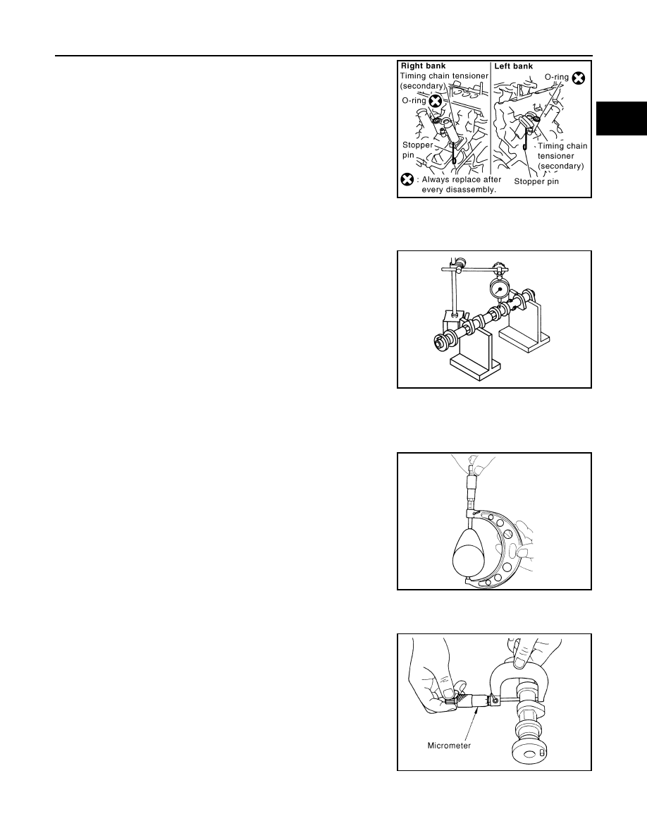
7.
Remove timing chain tensioner (secondary) from cylinder head.
• Remove timing chain tensioner (secondary) with its stopper
pin attached.
NOTE:
Stopper pin was attached when timing chain (secondary) was
removed.
INSPECTION AFTER REMOVAL
Camshaft Runout
1.
Put V-block on precise flat table, and support No. 2 and 4 journal
of camshaft.
CAUTION:
Do not support journal No. 1 (on the side of camshaft
sprocket) because it has a different diameter from the other
three locations.
2.
Set dial indicator vertically to No. 3 journal.
3.
Turn camshaft to one direction with hands, and measure the
camshaft runout on dial indicator. (Total indicator reading)
4.
If it exceeds the limit, replace camshaft.
Camshaft Cam Height
1.
Measure the camshaft cam height with micrometer.
2.
If wear exceeds the limit, replace camshaft.
Camshaft Journal Oil Clearance
CAMSHAFT JOURNAL DIAMETER
• Measure the outer diameter of camshaft journal with micrometer.
CAMSHAFT BRACKET INNER DIAMETER
• Tighten camshaft bracket bolt with the specified torque.
PBIC2111E
Standard
: Less than 0.02 mm (0.0008 in)
Limit
: 0.05 mm (0.0020 in)
PBIC0929E
Standard:
Intake
: 45.465 - 45.655 mm (1.7900 - 1.7974 in)
Exhaust
: 45.075 - 45.265 mm (1.7746 - 1.7821 in)
Limit:
Intake
: 45.265 mm (1.7821 in)
Exhaust
: 44.875 mm (1.7667 in)
EMQ0072D
Standard:
No. 1
: 25.935 - 25.955 mm (1.0211 - 1.0218 in)
No. 2, 3, 4
: 23.445 - 23.465 mm (0.9230 - 0.9238 in)
PBIC0040E