Nissan Pathfinder (2008 year). Manual - part 358
INTAKE MANIFOLD COLLECTOR
EM-27
< ON-VEHICLE REPAIR >
[VQ40DE]
C
D
E
F
G
H
I
J
K
L
M
A
EM
N
P
O
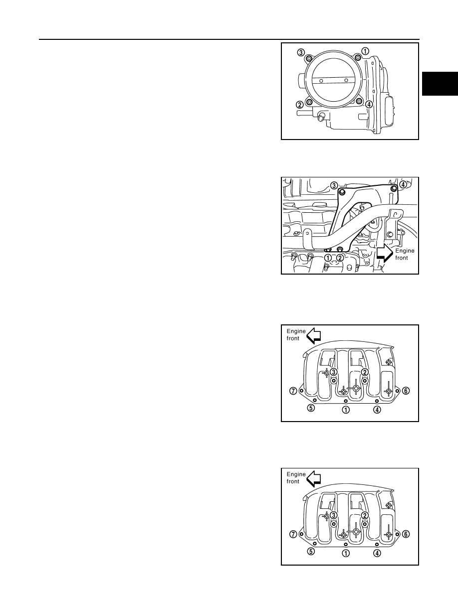
d.
Loosen bolts in reverse order as shown.
CAUTION:
• Handle carefully to avoid any shock to electric throttle
control actuator.
• Do not disassemble.
4.
Remove the following parts:
• Vacuum hose (to brake booster)
• PCV hose
5.
Loosen bolts in reverse order as shown to remove intake mani-
fold collector support.
6.
Disconnect EVAP hoses and harness connector from EVAP canister purge volume control solenoid valve.
7.
Remove EVAP canister purge volume control solenoid valve.
8.
Remove VIAS control solenoid valve and vacuum tank.
• Add mating marks as necessary for easier installation.
9.
Loosen nuts and bolts in reverse order as shown with power
tool, and remove intake manifold collector.
CAUTION:
Cover engine openings to avoid entry of foreign materials.
INSTALLATION
Installation is in the reverse order of removal. Note the following:
Intake Manifold Collector
• If stud bolts were removed from intake manifold, install them and tighten to the specified torque.
• Tighten nuts and bolts in numerical order as shown.
PBIC2875E
PBIC2876E
PBIC2877E
Intake manifold collector
bolts and nuts
: 11.0 N·m (1.1 kg-m, 8 ft-lb)
Stud bolts
: 6.9 N·m (7.0kg-m, 61 in-lb)
PBIC2877E