Nissan Pathfinder (2008 year). Manual - part 356


  Index      Manuals     Nissan Pathfinder (2008 year) - Service and Repair Manual


Search            copyright infringement  


Content      ..     354      355      356      357     ..


Nissan Pathfinder (2008 year). Manual - part 356


NOISE, VIBRATION AND HARSHNESS (NVH) TROUBLESHOOTING

EM-11

< FUNCTION DIAGNOSIS >

[VQ40DE]

C

D

E

F

G

H

I

J

K

L

M

A

EM

N

P

O

FUNCTION DIAGNOSIS

NOISE, VIBRATION AND HARSHNESS (NVH) TROUBLESHOOTING

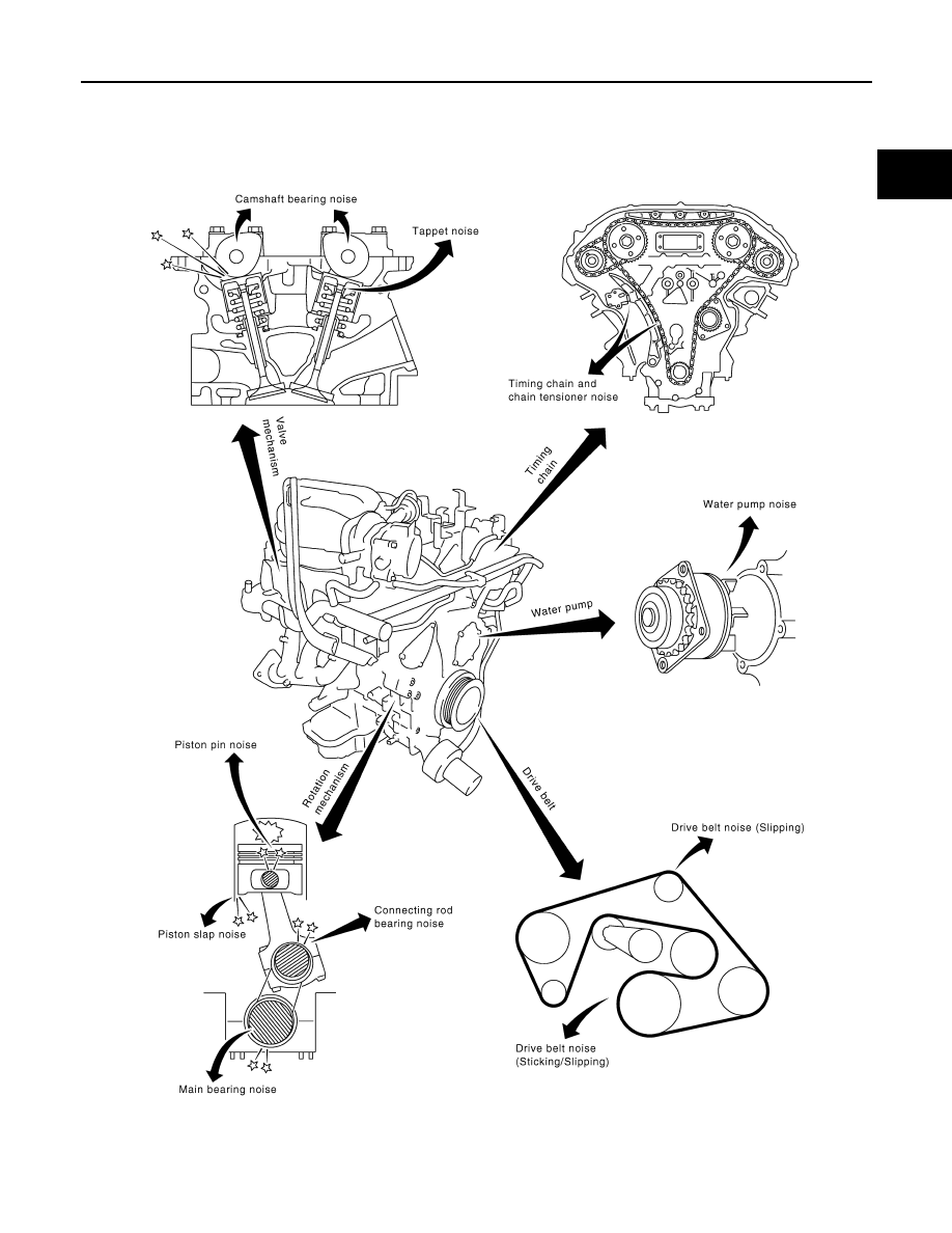
NVH Troubleshooting - Engine Noise

INFOID:0000000001281968

Use the Chart Below to Help You Find the Cause of the Symptom

INFOID:0000000001281969

1.

Locate the area where noise occurs.

PBIC2873E

EM-12

< FUNCTION DIAGNOSIS >

[VQ40DE]

NOISE, VIBRATION AND HARSHNESS (NVH) TROUBLESHOOTING

2.

Confirm the type of noise.

3.

Specify the operating condition of engine.

4.

Check specified noise source.

If necessary, repair or replace these parts.

A: Closely related

B: Related

C: Sometimes related

—: Not related

Location 

of noise

Type of 

noise

Operating condition of engine

Source of 

noise

Check item

Refer-

ence page

Before 

warm-

up

After 

warm-

up

When 

start-

ing

When 

idling

When 

racing

While 

driving

Top of en-
gine
Rocker 
cover
Cylinder 
head

Ticking or 
clicking

C

A

A

B

Tappet 
noise

Valve clearance

EM-18

Rattle

C

A

A

B

C

Camshaft 
bearing 
noise

Camshaft runout
Camshaft journal oil 
clearance

EM-81
EM-81

Crank-
shaft pul-
ley
Cylinder 
block 
(Side of 
engine)
Oil pan

Slap or 
knock

A

B

B

Piston pin 
noise

Piston to piston pin oil 
clearance
Connecting rod bushing 
oil clearance

EM-117


EM-117

Slap or 
rap

A

B

B

A

Piston 
slap noise

Piston to cylinder bore 
clearance
Piston ring side clear-
ance
Piston ring end gap
Connecting rod bend 
and torsion

EM-117
EM-117
EM-117
EM-117

Knock

A

B

C

B

B

B

Connect-
ing rod 
bearing 
noise

Connecting rod bushing 
oil clearance
Connecting rod bearing 
oil clearance

EM-117
EM-117

Knock

A

B

A

B

C

Main bear-
ing noise

Main bearing oil clear-
ance
Crankshaft runout

EM-117
EM-117

Front of 
engine
Timing 
chain case

Tapping or 
ticking

A

A

B

B

B

Timing 
chain and 
chain ten-
sioner 
noise

Timing chain cracks 
and wear
Timing chain tensioner 
operation

EM-61
EM-61

Front of 
engine

Squeak-
ing or fizz-
ing

A

B

B

C

Drive belts 
(Sticking 
or slip-
ping)

Drive belts deflection

EM-13

Creaking

A

B

A

B

A

B

Drive belts 
(Slipping)

Idler pulley bearing op-
eration

Squall
Creak

A

B

B

A

B

Water 
pump 
noise

Water pump operation

CO-22

Rattle

A

VTC

VTC lock pin clearance

EM-61

DRIVE BELTS

EM-13

< ON-VEHICLE MAINTENANCE >

[VQ40DE]

C

D

E

F

G

H

I

J

K

L

M

A

EM

N

P

O

ON-VEHICLE MAINTENANCE

DRIVE BELTS

Checking Drive Belts

INFOID:0000000001281971

WARNING:

Be sure to perform when the engine is stopped.

1.

Remove air duct and resonator assembly when inspecting drive belt. Refer to 

EM-25, "Removal and

Installation"

.

2.

Visually check entire belt for wear, damage or cracks.

Tension Adjustment

INFOID:0000000001281972

Belt tensioning is not necessary, as it is automatically adjusted by auto tensioner.

Removal and Installation

INFOID:0000000001281973

DRIVE BELT

Removal

1.

Remove air duct and resonator assembly. Refer to 

EM-25, "Removal and Installation"

.

2.

Rotate the drive belt auto tensioner in the direction of arrow
(loosening direction of tensioner) as shown, using suitable tool.

CAUTION:

Avoid placing hand in a location where pinching may occur
if the tool accidentally comes off.

3.

Remove the drive belt. 

Installation

Installation is in the reverse order of removal.

CAUTION:

Make sure belt is securely installed around all pulleys.

LBIA0427E

1.

Drive belt

2.

Power steering oil pump pulley

3.

Generator pulley

4.

Crankshaft pulley

5.

A/C compressor

6.

Cooling fan pulley

7.

Idler pulley

8.

Drive belt tensioner

LBIA0428E

EM-14

< ON-VEHICLE MAINTENANCE >

[VQ40DE]

DRIVE BELTS

Drive Belt Auto Tensioner and Idler Pulley

INFOID:0000000001281974

REMOVAL

1.

Remove air duct and resonator assembly. Refer to 

EM-25, "Removal and Installation"

.

2.

Remove drive belt. Refer to 

EM-13, "Removal and Installation"

.

3.

Remove engine cooling fan assembly (motor driven type). Refer to 

CO-20, "Removal and Installation

(Motor driven type)"

.

4.

Remove auto tensioner and idler pulley using power tool.

INSTALLATION

Installation is in the reverse order of removal.

LBIA0429E

1.

Idler pulley

2.

Drive belt auto tensioner

AIR CLEANER FILTER

EM-15

< ON-VEHICLE MAINTENANCE >

[VQ40DE]

C

D

E

F

G

H

I

J

K

L

M

A

EM

N

P

O

AIR CLEANER FILTER

Changing Air Cleaner Filter

INFOID:0000000001281976

REMOVAL

1.

Unhook clips, and lift air cleaner case (upper).

2.

Remove air cleaner filter.

INSTALLATION

Installation is in the reverse order of removal.

1.

Air cleaner case (lower)

2.

Air cleaner filter

3.

Air cleaner case (upper)

4.

Air duct and resonator

Front

AWBIA0133GB

EM-16

< ON-VEHICLE MAINTENANCE >

[VQ40DE]

SPARK PLUG

SPARK PLUG

Changing Spark Plugs

INFOID:0000000001281982

REMOVAL

1.

Remove the ignition coil. Refer to 

EM-41, "Removal and Installation"

.

2.

Remove the spark plug using a suitable tool.

CAUTION:

Do not drop or shock it.

INSPECTION AFTER REMOVAL

• Do not use a wire brush to clean the spark plug.

• If plug tip is covered with carbon, spark plug cleaner may be used.

1.

Ignition coil

2.

Spark plug

PBIC2901E

SEM294A

SMA773C

Cleaner air pressure

: Less than 588 kPa (5.9 bar, 6 kg/cm

2

, 85 psi)

Cleaning time

: Less than 20 seconds

SPARK PLUG

EM-17

< ON-VEHICLE MAINTENANCE >

[VQ40DE]

C

D

E

F

G

H

I

J

K

L

M

A

EM

N

P

O

• Checking and adjusting plug gap is not required between change

intervals.

INSTALLATION

Installation is in the reverse order of removal.

CAUTION:

Do not drop or shock the spark plug.

SMA806CA

Make

NGK

Standard type

DILFR5A-11

Gap (nominal)

1.1 mm (0.043 in)

EM-18

< ON-VEHICLE MAINTENANCE >

[VQ40DE]

CAMSHAFT VALVE CLEARANCE

CAMSHAFT VALVE CLEARANCE

Valve Clearance

INFOID:0000000001281988

INSPECTION

NOTE:
Perform the following inspection after removal, installation or replacement of camshaft or valve-related parts,
or if there are unusual engine conditions due to changes in valve clearance over time (starting, idling, and/or
noise).
1.

Warm up the engine. Then stop the engine.

2.

Remove rocker covers (right and left banks). Refer to 

EM-42, "Removal and Installation"

.

3.

Measure the valve clearance as follows:

a.

Set No. 1 cylinder at TDC of its compression stroke.
• Rotate crankshaft pulley clockwise to align timing mark

(grooved line without color) with timing indicator.

• Make sure that intake and exhaust cam noses on No. 1 cylin-

der (engine front side of RH bank) are located as shown.

• If not, rotate crankshaft one revolution (360

°

) and align as

shown.

b.

Use feeler gauge, measure the clearance between valve lifter
and camshaft.

Valve clearance:

Unit: mm (in)

*: Approximately 80

°

C (176

°

F)

KBIA1717J

SEM418G

SEM139D

Cold

Hot * (reference data)

Intake

0.26 - 0.34 (0.010 - 0.013)

0.304 - 0.416 (0.012 - 0.016)

Exhaust

0.29 - 0.37 (0.011 - 0.015)

0.308 - 0.432 (0.012 - 0.017)


Content      ..     354      355      356      357     ..