Nissan Pathfinder (2008 year). Manual - part 302
ON BOARD DIAGNOSTIC (OBD) SYSTEM
EC-533
< FUNCTION DIAGNOSIS >
[VK56DE]
C
D
E
F
G
H
I
J
K
L
M
A
EC
N
P
O
HOW TO ERASE EMISSION-RELATED DIAGNOSTIC INFORMATION
How to Erase DTC
WITH CONSULT-III
The emission related diagnostic information in the ECM can be erased by selecting “All Erase” in the “Descrip-
tion” of “FINAL CHECK” mode with CONSULT-III.
WITH GST
The emission related diagnostic information in the ECM can be erased by selecting Service $04 with GST.
NOTE:
If the DTC is not for A/T related items (see
), skip step 2.
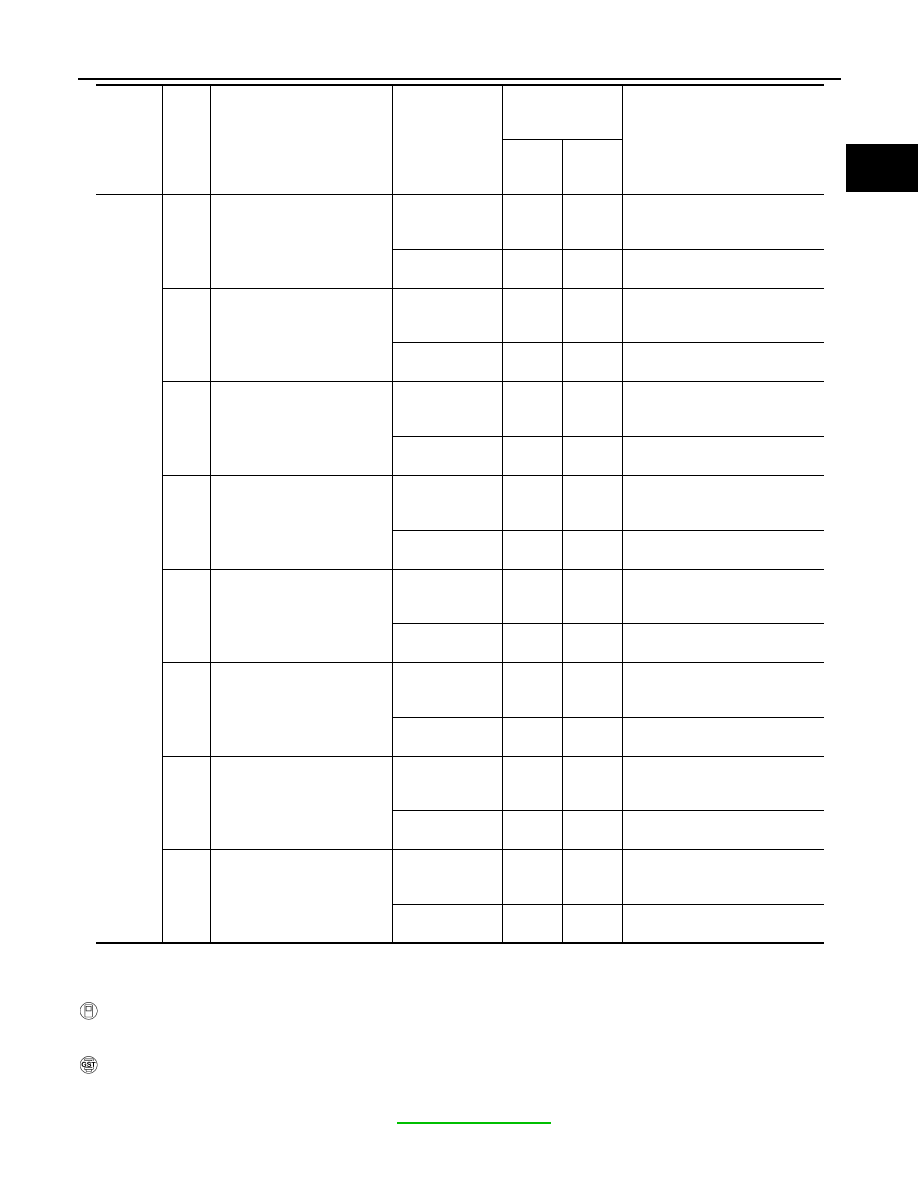
MISFIRE
A2H
No.1 Cylinder Misfire
P0301
0BH
24H
EWMA (Exponential Weighted
Moving Average) misfire counts
for last 10 driving cycles
P0301
0CH
24H
Misfire counts for last/current driv-
ing cycles
A3H
No.2 Cylinder Misfire
P0302
0BH
24H
EWMA (Exponential Weighted
Moving Average) misfire counts
for last 10 driving cycles
P0302
0CH
24H
Misfire counts for last/current driv-
ing cycles
A4H
No.3 Cylinder Misfire
P0303
0BH
24H
EWMA (Exponential Weighted
Moving Average) misfire counts
for last 10 driving cycles
P0303
0CH
24H
Misfire counts for last/current driv-
ing cycles
A5H
No.4 Cylinder Misfire
P0304
0BH
24H
EWMA (Exponential Weighted
Moving Average) misfire counts
for last 10 driving cycles
P0304
0CH
24H
Misfire counts for last/current driv-
ing cycles
A6H
No.5 Cylinder Misfire
P0305
0BH
24H
EWMA (Exponential Weighted
Moving Average) misfire counts
for last 10 driving cycles
P0305
0CH
24H
Misfire counts for last/current driv-
ing cycles
A7H
No.6 Cylinder Misfire
P0306
0BH
24H
EWMA (Exponential Weighted
Moving Average) misfire counts
for last 10 driving cycles
P0306
0CH
24H
Misfire counts for last/current driv-
ing cycles
A8H
No.7 Cylinder Misfire
P0307
0BH
24H
EWMA (Exponential Weighted
Moving Average) misfire counts
for last 10 driving cycles
P0307
0CH
24H
Misfire counts for last/current driv-
ing cycles
A9H
No.8 Cylinder Misfire
P0308
0BH
24H
EWMA (Exponential Weighted
Moving Average) misfire counts
for last 10 driving cycles
P0308
0CH
24H
Misfire counts for last/current driv-
ing cycles
Item
OBD-
MID
Self-diagnostic test item
DTC
Test value and Test
limit
(GST display)
Description
TID
Unit and
Scaling
ID