Nissan Pathfinder (2008 year). Manual - part 300
EVAPORATIVE EMISSION SYSTEM
EC-517
< FUNCTION DIAGNOSIS >
[VK56DE]
C
D
E
F
G
H
I
J
K
L
M
A
EC
N
P
O
EVAPORATIVE EMISSION SYSTEM
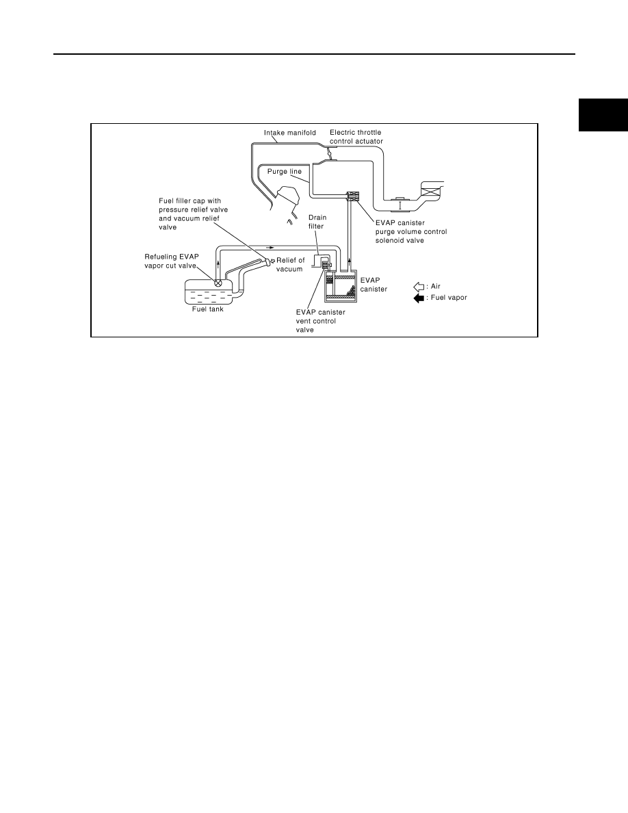
Description
INFOID:0000000001537612
SYSTEM DESCRIPTION
The evaporative emission system is used to reduce hydrocarbons emitted into the atmosphere from the fuel
system. This reduction of hydrocarbons is accomplished by activated charcoals in the EVAP canister.
The fuel vapor in the sealed fuel tank is led into the EVAP canister which contains activated carbon and the
vapor is stored there when the engine is not operating or when refueling to the fuel tank.
The vapor in the EVAP canister is purged by the air through the purge line to the intake manifold when the
engine is operating. EVAP canister purge volume control solenoid valve is controlled by ECM. When the
engine operates, the flow rate of vapor controlled by EVAP canister purge volume control solenoid valve is
proportionally regulated as the air flow increases.
EVAP canister purge volume control solenoid valve also shuts off the vapor purge line during decelerating and
idling.
PBIB3639E