Nissan Pathfinder (2008 year). Manual - part 298


  Index      Manuals     Nissan Pathfinder (2008 year) - Service and Repair Manual


Search            copyright infringement  


Content      ..     296      297      298      299     ..


Nissan Pathfinder (2008 year). Manual - part 298


ENGINE CONTROL SYSTEM

EC-501

< FUNCTION DIAGNOSIS >

[VK56DE]

C

D

E

F

G

H

I

J

K

L

M

A

EC

N

P

O

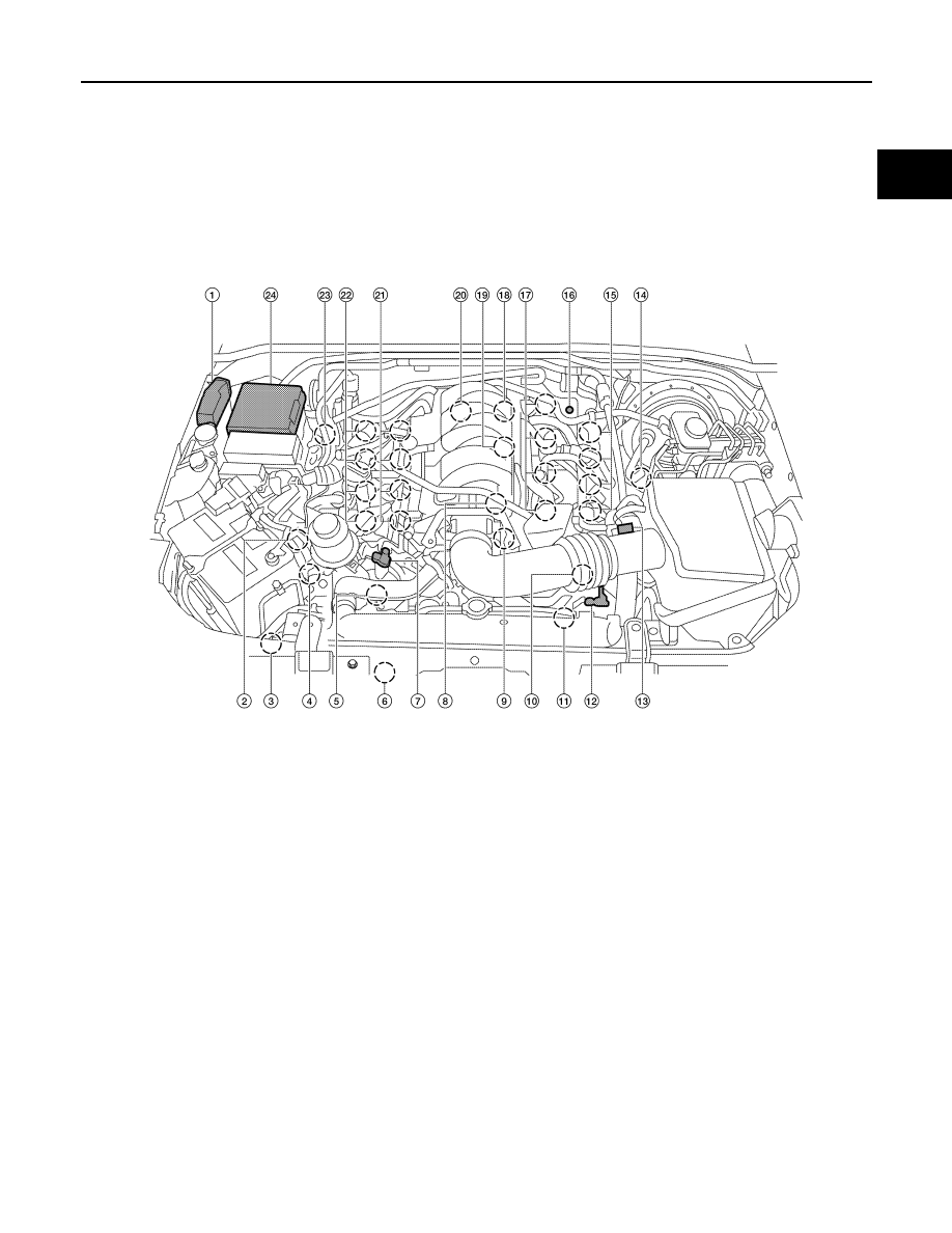
Engine Control Component Parts Location

INFOID:0000000001537603

1.

ECM

2.

Battery current sensor

3.

Refrigerant pressure sensor

4.

Power steering pressure sensor

5.

Intake valve timing control solenoid 
valve (bank 2)

6.

Cooling fan motor

7.

Intake valve timing control position 
sensor (bank 2)

8.

Engine coolant temperature sensor

9.

Electric throttle control actuator

10. Intake valve timing control position 

sensor (bank 1)

11.

Intake valve timing control solenoid 
valve (bank 1)

12. Camshaft position sensor (PHASE)

13. Mass air flow sensor (with intake air 

temperature sensor)

14. A/F sensor 1 (bank 1)

15. Ignition coil (with power transistor) 

and spark plug (bank 1)

16. EVAP service port 

17. Fuel injector (bank 1)

18. Knock sensor (bank 1)

19. EVAP canister purge volume control 

solenoid valve

20. Knock sensor (bank 2)

21. Fuel injector (bank 2)

22. Ignition coil (with power transistor) 

and spark plug (bank 2)

23. A/F sensor 1 (bank 2)

24. IPDM E/R

ALBIA0352ZZ

EC-502

< FUNCTION DIAGNOSIS >

[VK56DE]

ENGINE CONTROL SYSTEM

1.

Body ground (view with air cleaner 
case removed)

2.

Body ground (view with battery re-
moved)

3.

No.1 ignition coil

4.

Engine ground

5.

Mass air flow sensor (with intake air 
temperature sensor)

6.

IPDM E/R

7.

Battery

8.

Radiator hose

9.

Camshaft position sensor (PHASE)

AWBIA0081ZZ

ENGINE CONTROL SYSTEM

EC-503

< FUNCTION DIAGNOSIS >

[VK56DE]

C

D

E

F

G

H

I

J

K

L

M

A

EC

N

P

O

10. Electric throttle control actuator 

(view with intake air duct removed)

11.

Electronic throttle control actuator 
harness connector (view with intake 
air duct removed)

12. Cooling fan motor harness connec-

tor

: Vehicle front

AWBIA0082ZZ

EC-504

< FUNCTION DIAGNOSIS >

[VK56DE]

ENGINE CONTROL SYSTEM

1.

EVAP canister purge volume control 
solenoid valve (view with engine 
cover removed)

2.

EVAP service port 

3.

Crankshaft position sensor (POS) 
(view from under vehicle)

4.

Engine oil pan 

5.

Condenser-1

6.

Brake fluid reservoir

7.

Fuel filler pipe (top of frame view)

8.

EVAP control system pressure sen-
sor

9.

EVAP canister vent control valve

10. EVAP canister

11.

Drain filter

12. Refrigerant pressure sensor

13. Intake valve timing control position 

sensor (bank 2) (view with engine 
cover and intake air duct removed)

14. Intake valve timing control position 

sensor (bank 1) 

15. Intake valve timing control solenoid 

valve (bank 2) (view with engine cov-
er and intake air duct removed)

16. Drive belt

17. Radiator hose (view with engine cov-

er and intake air duct removed)

18

Intake valve timing control solenoid 
valve (bank 1) 

: Vehicle front

ALBIA0369ZZ

1.

Knock sensor (bank 1) (view with en-
gine removed)

2.

Knock sensor (bank 2) (view with en-
gine removed)

3.

Battery current sensor

4.

Power steering pressure sensor

5.

Intake manifold

6.

Engine coolant temperature sensor

ENGINE CONTROL SYSTEM

EC-505

< FUNCTION DIAGNOSIS >

[VK56DE]

C

D

E

F

G

H

I

J

K

L

M

A

EC

N

P

O

7.

Ignition coil (with power transistor) 
(bank2)

8.

Ignition coil (with power transistor) 
(bank 1)

9.

Fuel injector harness connectors 
(bank 2)

10. Fuel injector harness connectors 

(bank 1)

: Vehicle front

PBIB2710E

1.

A/F sensor 1 (bank 2)

2.

A/F sensor 1(bank 1)

3.

Heated oxygen sensor 2
(bank 1)

4.

Heated oxygen sensor 2
(bank 2)

: Vehicle front

AWBIA0083ZZ

EC-506

< FUNCTION DIAGNOSIS >

[VK56DE]

ENGINE CONTROL SYSTEM

1.

ASCD steering switch

2.

MAIN switch

3.

CANCEL switch

4.

SET/COAST switch

5.

RESUME/ACCELERATE switch

6.

ECM harness connectors (view with 
ECM cover removed)

7.

Coolant reservoir

8.

Accelerator pedal position sensor

9.

Fuel level sensor unit and fuel pump 
harness connector (view with fuel 
tank removed)

AWBIA0084ZZ

ENGINE CONTROL SYSTEM

EC-507

< FUNCTION DIAGNOSIS >

[VK56DE]

C

D

E

F

G

H

I

J

K

L

M

A

EC

N

P

O

10. Fuel pump, fuel level sensor unit and 

fuel filter

11.

Fuel pressure regulator

12. ASCD brake switch

13. Stop lamp switch

14. Brake pedal

EC-508

< FUNCTION DIAGNOSIS >

[VK56DE]

MULTIPORT FUEL INJECTION SYSTEM

MULTIPORT FUEL INJECTION SYSTEM

System Description

INFOID:0000000001537604

INPUT/OUTPUT SIGNAL CHART

*1: This sensor is not used to control the engine system. This is used only for the on board diagnosis.

*2: This signal is sent to the ECM through CAN communication line.

*3: ECM determines the start signal status by the signals of engine speed and battery voltage.

SYSTEM DESCRIPTION

The amount of fuel injected from the fuel injector is determined by the ECM. The ECM controls the length of
time the valve remains open (injection pulse duration). The amount of fuel injected is a program value in the
ECM memory. The program value is preset by engine operating conditions. These conditions are determined
by input signals (for engine speed and intake air) from both the crankshaft position sensor and the mass air
flow sensor.

VARIOUS FUEL INJECTION INCREASE/DECREASE COMPENSATION

In addition, the amount of fuel injected is compensated to improve engine performance under various operat-
ing conditions as listed below.

<Fuel increase>

• During warm-up
• When starting the engine
• During acceleration
• Hot-engine operation
• When selector lever is changed from N to D
• High-load, high-speed operation

<Fuel decrease>

• During deceleration
• During high engine speed operation

Sensor

Input signal to ECM

ECM function

Actuator

Crankshaft position sensor (POS)

Engine speed*

3

Piston position

Fuel injection 
& mixture ratio 
control

Fuel injector

Camshaft position sensor (PHASE)

Mass air flow sensor

Amount of intake air

Engine coolant temperature sensor

Engine coolant temperature

Air fuel ratio (A/F) sensor 1

Density of oxygen in exhaust gas

Throttle position sensor

Throttle position

Accelerator pedal position sensor

Accelerator pedal position

Park/neutral position (PNP) switch

Gear position

Knock sensor

Engine knocking condition

Battery

Battery voltage*

3

Power steering pressure sensor

Power steering operation

Heated oxygen sensor 2*

1

Density of oxygen in exhaust gas

ABS actuator and electric unit (control unit)

VDC/TCS operation command*

2

Air conditioner switch

Air conditioner operation*

2

Wheel sensor

Vehicle speed*

2


Content      ..     296      297      298      299     ..