Nissan Pathfinder (2008 year). Manual - part 245


  Index      Manuals     Nissan Pathfinder (2008 year) - Service and Repair Manual


Search            copyright infringement  


Content      ..     243      244      245      246     ..


Nissan Pathfinder (2008 year). Manual - part 245


ON BOARD DIAGNOSTIC (OBD) SYSTEM

EC-77

< FUNCTION DIAGNOSIS >

[VQ40DE]

C

D

E

F

G

H

I

J

K

L

M

A

EC

N

P

O

*: This function is not necessary in the usual service procedure.

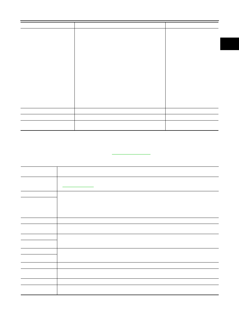
SELF-DIAG RESULTS MODE

Self Diagnostic Item

Regarding items of DTC and 1st trip DTC, refer to 

EC-453, "DTC Index"

.

Freeze Frame Data and 1st Trip Freeze Frame Data

EVAP SYSTEM CLOSE

CLOSE THE EVAP CANISTER VENT CONTROL VALVE IN 
ORDER TO MAKE EVAP SYSTEM CLOSE UNDER THE 
FOLLOWING CONDITIONS.
• IGN  SW  ON
• ENGINE NOT RUNNING
• AMBIENT TEMPERATURE IS ABOVE 0

°

C (32

°

F).

• NO VACUUM AND NO HIGH PRESSURE IN EVAP SYS-

TEM

•  FUEL TANK TEMP. IS MORE THAN 0

°

C (32

°

F).

• WITHIN 10 MINUTES AFTER STARTING “EVAP SYS-

TEM CLOSE”

• WHEN TRYING TO EXECUTE “EVAP SYSTEM CLOSE” 

UNDER THE CONDITION EXCEPT ABOVE, CONSULT-
III WILL DISCONTINUE IT AND DISPLAY APPROPRI-
ATE INSTRUCTION.
NOTE:
WHEN STARTING ENGINE, CONSULT-III MAY DIS-
PLAY “BATTERY VOLTAGE IS LOW. CHARGE BAT-
TERY”, EVEN IN USING CHARGED BATTERY.

When detecting EVAP vapor leak 
point of EVAP system

VIN REGISTRATION

• IN THE MODE, VIN IS REGISTERED IN ECM.

When registering VIN in ECM

TARGET IDLE RPM ADJ*

• IDLE CONDITION

When setting target idle speed

TARGET IGN TIM ADJ*

• IDLE CONDITION

When adjusting target ignition tim-
ing

WORK ITEM

CONDITION

USAGE

Freeze frame data 

item*

Description

DIAG TROUBLE 
CODE
[PXXXX]

• The engine control component part/control system has a trouble code, it is displayed as PXXXX. (Refer to 

EC-453, "DTC Index"

.)

FUEL SYS-B1

• “Fuel injection system status” at the moment a malfunction is detected is displayed.
• One mode in the following is displayed.

Mode2: Open loop due to detected system malfunction
Mode3: Open loop due to driving conditions (power enrichment, deceleration enleanment)
Mode4: Closed loop - using oxygen sensor(s) as feedback for fuel control
Mode5: Open loop - has not yet satisfied condition to go to closed loop

FUEL SYS-B2

CAL/LD VALUE [%]

• The calculated load value at the moment a malfunction is detected is displayed.

COOLANT TEMP [

°

C] 

or [

°

F]

• The engine coolant temperature at the moment a malfunction is detected is displayed.

L-FUEL TRM-B1 [%]

• “Long-term fuel trim” at the moment a malfunction is detected is displayed.
• The long-term fuel trim indicates much more gradual feedback compensation to the base fuel schedule than 

short-term fuel trim.

L-FUEL TRM-B2 [%]

S-FUEL TRM-B1 [%]

• “Short-term fuel trim” at the moment a malfunction is detected is displayed.
• The short-term fuel trim indicates dynamic or instantaneous feedback compensation to the base fuel sched-

ule.

S-FUEL TRM-B2 [%]

ENGINE SPEED [rpm]

• The engine speed at the moment a malfunction is detected is displayed.

VEHICL SPEED [km/
h] or [mph]

• The vehicle speed at the moment a malfunction is detected is displayed.

ABSOL TH-P/S [%]

• The throttle valve opening angle at the moment a malfunction is detected is displayed.

B/FUEL SCHDL 
[msec]

• The base fuel schedule at the moment a malfunction is detected is displayed.

EC-78

< FUNCTION DIAGNOSIS >

[VQ40DE]

ON BOARD DIAGNOSTIC (OBD) SYSTEM

*: The items are the same as those of 1st trip freeze frame data.

DATA MONITOR MODE

Monitored Item

×

: Applicable

INT/A TEMP SE [

°

C] 

or [

°

F]

• The intake air temperature at the moment a malfunction is detected is displayed.

INT MANI PRES [kPa]

• Always a certain value is displayed.
• These items can not efficiently for R51 models.

FTFMCHI

Freeze frame data 

item*

Description

Monitored item

Unit

Description

Remarks

ENG SPEED

rpm

• Indicates the engine speed computed from the sig-

nal of the crankshaft position sensor (POS) and 
camshaft position sensor (PHASE).

• Accuracy becomes poor if engine speed 

drops below the idle rpm.

• If the signal is interrupted while the en-

gine is running, an abnormal value may 
be indicated.

MAS A/F SE-B1

V

• The signal voltage of the mass air flow sensor is 

displayed.

• When the engine is stopped, a certain 

value is indicated.

• When engine is runnning specification 

range is indicated in “SPEC”.

B/FUEL SCHDL

msec

• “Base fuel schedule” indicates the fuel injection 

pulse width programmed into ECM, prior to any 
learned on board correction.

• When engine is runnning specification 

range is indicated in “SPEC”.

A/F ALPHA-B1

%

• The mean value of the air-fuel ratio feedback cor-

rection factor per cycle is indicated.

• When the engine is stopped, a certain 

value is indicated.

• When engine is runnning specification 

range is indicated in “SPEC”.

• This data also includes the data for the 

air-fuel ratio learning control.

A/F ALPHA-B2

%

COOLAN TEMP/S

°

C or 

°

F

• The engine coolant temperature (determined by 

the signal voltage of the engine coolant tempera-
ture sensor) is displayed.

• When the engine coolant temperature 

sensor is open or short-circuited, ECM 
enters fail-safe mode. The engine cool-
ant temperature determined by the ECM 
is displayed.

A/F SEN1 (B1)

V

• The A/F signal computed from the input signal of 

the Air fuel ratio (A/F) sensor 1 is displayed.

A/F SEN1 (B2)

V

HO2S2 (B1)

V

• The signal voltage of the heated oxygen sensor 2 

is displayed.

HO2S2 (B2)

V

HO2S2 MNTR (B1)

RICH/

LEAN

• Display of heated oxygen sensor 2 signal:

RICH: Means the amount of oxygen after three way 
catalyst is relatively small.
LEAN: Means the amount of oxygen after three 
way catalyst is relatively large.

• When the engine is stopped, a certain 

value is indicated.

HO2S2 MNTR (B2)

RICH/

LEAN

VHCL SPEED SE

km/h or 

mph

• The vehicle speed computed from the vehicle 

speed signal sent from combination meter is dis-
played.

BATTERY VOLT

V

• The power supply voltage of ECM is displayed.

ACCEL SEN 1

V

• The accelerator pedal position sensor signal volt-

age is displayed.

• ACCEL SEN 2 signal is converted by 

ECM internally. Thus, it differs from ECM 
terminal voltage signal.

ACCEL SEN 2

V

TP SEN 1-B1

V

• The throttle position sensor signal voltage is dis-

played.

• THRTL SEN 2 signal is converted by 

ECM internally. Thus, it differs from ECM 
terminal voltage signal.

TP SEN 2-B1

V

FUEL T/TMP SE

°

C or 

°

F

• The fuel temperature (determined by the signal 

voltage of the fuel tank temperature sensor) is dis-
played.

ON BOARD DIAGNOSTIC (OBD) SYSTEM

EC-79

< FUNCTION DIAGNOSIS >

[VQ40DE]

C

D

E

F

G

H

I

J

K

L

M

A

EC

N

P

O

INT/A TEMP SE

°

C or 

°

F

• The intake air temperature (determined by the sig-

nal voltage of the intake air temperature sensor) is 
indicated.

EVAP SYS PRES

V

FUEL LEVEL SE

V

START SIGNAL

ON/OFF

• Indicates start signal status [ON/OFF] computed by 

the ECM according to the signals of engine speed 
and battery voltage.

• After starting the engine, [OFF] is dis-

played regardless of the starter signal.

CLSD THL POS

ON/OFF

• Indicates idle position [ON/OFF] computed by ECM 

according to the accelerator pedal position sensor 
signal.

AIR COND SIG

ON/OFF

• Indicates [ON/OFF] condition of the air conditioner 

switch as determined by the air conditioner signal.

P/N POSI SW

ON/OFF

• Indicates [ON/OFF] condition from the park/neutral 

position (PNP) switch signal.

PW/ST SIGNAL

ON/OFF

• [ON/OFF] condition of the power steering system 

(determined by the signal voltage of the power 
steering pressure sensor signal) is indicated.

LOAD SIGNAL

ON/OFF

• Indicates [ON/OFF] condition from the electrical 

load signal.
ON: Rear window defogger switch is ON and/or 
lighting switch is in 2nd position.
OFF: Both rear window defogger switch and light-
ing switch are OFF.

IGNITION SW

ON/OFF

• Indicates [ON/OFF] condition from ignition switch 

signal.

HEATER FAN SW

ON/OFF

• Indicates [ON/OFF] condition from the heater fan 

switch signal.

BRAKE SW

ON/OFF

• Indicates [ON/OFF] condition from the stop lamp 

switch signal.

INJ PULSE-B1

msec

• Indicates the actual fuel injection pulse width com-

pensated by ECM according to the input signals.

• When the engine is stopped, a certain 

computed value is indicated.

INJ PULSE-B2

msec

IGN TIMING

BTDC

• Indicates the ignition timing computed by ECM ac-

cording to the input signals.

• When the engine is stopped, a certain 

value is indicated.

CAL/LD VALUE

%

• Calculated load value indicates the value of the 

current air flow divided by peak air flow.

MASS AIRFLOW

g·m/s

• Indicates the mass air flow computed by ECM ac-

cording to the signal voltage of the mass air flow 
sensor.

PURG VOL C/V

%

• Indicates the EVAP canister purge volume control 

solenoid valve control value computed by the ECM 
according to the input signals.

• The opening becomes larger as the value increas-

es.

INT/V TIM (B1)

°

CA

• Indicates [

°

CA] of intake camshaft advanced angle. 

INT/V TIM (B2)

°

°

CA

INT/V SOL (B1)

%

• The control condition of the intake valve timing con-

trol solenoid valve (determined by ECM according 
to the input signals) is indicated.

• The advance angle becomes larger as the value in-

creases.

INT/V SOL (B2)

%

Monitored item

Unit

Description

Remarks

EC-80

< FUNCTION DIAGNOSIS >

[VQ40DE]

ON BOARD DIAGNOSTIC (OBD) SYSTEM

VIAS S/V-1

ON/OFF

• The control condition of the VIAS control solenoid 

valve (determined by ECM according to the input 
signals) is indicated.
ON: VIAS control solenoid valve is operating.
OFF: VIAS control solenoid valve is not operating.

AIR COND RLY

ON/OFF

• The air conditioner relay control condition (deter-

mined by ECM according to the input signals) is in-
dicated.

FUEL PUMP RLY

ON/OFF

• Indicates the fuel pump relay control condition de-

termined by ECM according to the input signals.

VENT CONT/V

ON/OFF

• The control condition of the EVAP canister vent 

control valve (determined by ECM according to the 
input signals) is indicated.
ON: Closed
OFF: Open

THRTL RELAY

ON/OFF

• Indicates the throttle control motor relay control 

condition determined by the ECM according to the 
input signals.

COOLING FAN

HI/LOW/

OFF

• The control condition of the cooling fan (deter-

mined by ECM according to the input signals) is in-
dicated.
HI: High speed operation
LOW: Low speed operation
OFF: Stop

HO2S2 HTR (B1)

ON/OFF

• Indicates [ON/OFF] condition of heated oxygen 

sensor 2 heater determined by ECM according to 
the input signals.

HO2S2 HTR (B2)

ON/OFF

I/P PULLY SPD

rpm

• Indicates the engine speed computed from the tur-

bine revolution sensor signal.

VEHICLE SPEED

km/h or 

mph

• Indicates the vehicle speed computed from the rev-

olution sensor signal.

IDL A/V LEARN

YET/

CMPLT

• Display the condition of idle air volume learning

YET: Idle air volume learning has not been per-
formed yet.
CMPLT: Idle air volume learning has already been 
performed successfully.

TRVL AFTER MIL

km or 

mile

• Distance traveled while MIL is activated.

A/F S1 HTR (B1)

%

• Air fuel ratio (A/F) sensor 1 heater control value 

computed by ECM according to the input signals.

• The current flow to the heater becomes larger as 

the value increases.

A/F S1 HTR (B2)

%

AC PRESS SEN

V

• The signal voltage from the refrigerant pressure 

sensor is displayed.

VHCL SPEED SE

km/h or 

mph

• The vehicle speed computed from the vehicle 

speed signal sent from TCM is displayed.

SET VHCL SPD

km/h or 

mph

• The preset vehicle speed is displayed.

MAIN SW

ON/OFF

• Indicates [ON/OFF] condition from MAIN switch 

signal.

CANCEL SW

ON/OFF

• Indicates [ON/OFF] condition from CANCEL switch 

signal.

RESUME/ACC SW

ON/OFF

• Indicates [ON/OFF] condition from RESUME/AC-

CELERATE switch signal.

SET SW

ON/OFF

• Indicates [ON/OFF] condition from SET/COAST 

switch signal.

Monitored item

Unit

Description

Remarks

ON BOARD DIAGNOSTIC (OBD) SYSTEM

EC-81

< FUNCTION DIAGNOSIS >

[VQ40DE]

C

D

E

F

G

H

I

J

K

L

M

A

EC

N

P

O

NOTE:

Any monitored item that does not match the vehicle being diagnosed is deleted from the display automatically.

ACTIVE TEST MODE

Test Item

BRAKE SW1

ON/OFF

• Indicates [ON/OFF] condition from ASCD brake 

switch signal.

BRAKE SW2

ON/OFF

• Indicates [ON/OFF] condition of stop lamp switch 

signal.

VHCL SPD CUT

NON/

CUT

• Indicates the vehicle cruise condition.

NON: Vehicle speed is maintained at the ASCD set 
speed.
CUT: Vehicle speed increased to excessively high 
compared with the ASCD set speed, and ASCD op-
eration is cut off.

LO SPEED CUT

NON/

CUT

• Indicates the vehicle cruise condition.

NON: Vehicle speed is maintained at the ASCD set 
speed.
CUT: Vehicle speed decreased to excessively low 
compared with the ASCD set speed, and ASCD op-
eration is cut off.

AT OD MONITOR

ON/OFF

• Indicates [ON/OFF] condition of A/T O/D according 

to the input signal from the TCM.

AT OD CANCEL

ON/OFF

• Indicates [ON/OFF] condition of A/T O/D cancel 

signal sent from the TCM.

CRUISE LAMP

ON/OFF

• Indicates [ON/OFF] condition of CRUISE lamp de-

termined by the ECM according to the input sig-
nals.

SET LAMP

ON/OFF

• Indicates [ON/OFF] condition of SET lamp deter-

mined by the ECM according to the input signals.

ALT DUTY

%

• Indicates the duty ratio of the power generation 

command value. The ratio is calculated by ECM 
based on the battery current sensor signal.

BAT CUR SEN

mV

• The signal voltage of battery current sensor is dis-

played.

ALT DUTY SIG [ON/
OFF]

ON/OFF

• The control condition of the power generation volt-

age variable control (determined by ECM accord-
ing to the input signals) is indicated.
ON: Power generation voltage variable control is 
active
OFF: Power generation voltage variable control is 
inactive.

A/F ADJ-B1

• Indicates the correction factor stored in ECM. The 

factor is calculated from the difference between the 
target air-fuel ratio stored in ECM and the air-fuel 
ratio calculated from A/F sensor 1 signal.

A/F ADJ-B2

Monitored item

Unit

Description

Remarks

TEST ITEM

CONDITION

JUDGEMENT

CHECK ITEM (REMEDY)

FUEL INJEC-
TION

• Engine: Return to the original 

trouble condition

• Change the amount of fuel injec-

tion using CONSULT-III.

If trouble symptom disappears, see 
CHECK ITEM.

• Harness and connectors
• Fuel injector
• Air fuel ratio (A/F) sensor 1

IGNITION TIM-
ING

• Engine: Return to the original 

trouble condition

• Timing light: Set
• Retard the ignition timing using 

CONSULT-III.

If trouble symptom disappears, see 
CHECK ITEM.

• Perform Idle Air Volume Learning.

EC-82

< FUNCTION DIAGNOSIS >

[VQ40DE]

ON BOARD DIAGNOSTIC (OBD) SYSTEM

*: Leaving cooling fan OFF with CONSULT-III while engine is running may cause the engine to overheat.

DTC & SRT CONFIRMATION MODE

SRT STATUS Mode

For details, refer to 

EC-54, "Emission-related Diagnostic Information"

.

SRT Work Support Mode

This mode enables a technician to drive a vehicle to set the SRT while monitoring the SRT status.

DTC Work Support Mode

POWER BAL-
ANCE

• Engine: After warming up, idle the 

engine.

• A/C switch: OFF
• Shift lever: P or N
• Cut off each fuel injector signal 

one at a time using CONSULT-III.

Engine runs rough or dies.

• Harness and connectors
• Compression
• Fuel injector
• Power transistor
• Spark  plug
• Ignition coil

COOLING FAN*

• Ignition  switch:  ON
• Turn the cooling fan HI, LOW and 

OFF using CONSULT-III.

Cooling fan moves and stops.

• Harness and connectors
• Cooling fan motor
• IPDM E/R

ENG COOLANT 
TEMP

• Engine: Return to the original 

trouble condition

• Change the engine coolant tem-

perature using CONSULT-III.

If trouble symptom disappears, see 
CHECK ITEM.

• Harness and connectors
• Engine coolant temperature sen-

sor

• Fuel injector

FUEL PUMP RE-
LAY

• Ignition switch: ON (Engine 

stopped)

• Turn the fuel pump relay ON and 

OFF using CONSULT-III and lis-
ten to operating sound.

Fuel pump relay makes the operat-
ing sound.

• Harness and connectors
• Fuel  pump  relay

VIAS SOL VALVE

• Ignition  switch:  ON
• Turn solenoid valve ON and OFF 

with CONSULT-III and listen for 
operating sound.

Solenoid valve makes an operating 
sound.

• Harness and connectors
• Solenoid valve

PURG VOL 
CONT/V

• Engine: After warming up, run en-

gine at 1,500 rpm.

• Change the EVAP canister purge 

volume control solenoid valve 
opening percent using CON-
SULT-III.

Engine speed changes according to 
the opening percent.

• Harness and connectors
• Solenoid valve

FUEL/T TEMP 
SEN

• Change the fuel tank temperature using CONSULT-III.

VENT CON-
TROL/V

• Ignition switch: ON (Engine 

stopped)

• Turn solenoid valve ON and OFF 

with the CONSULT-III and listen 
to operating sound.

Solenoid valve makes an operating 
sound.

• Harness and connectors
• Solenoid valve

V/T ASSIGN AN-
GLE

• Engine: Return to the original 

trouble condition

• Change intake valve timing using 

CONSULT-III.

If trouble symptom disappears, see 
CHECK ITEM.

• Harness and connectors
• Intake valve timing control sole-

noid valve

ALTERNATOR 
DUTY

• Engine:  Idle
• Change duty ratio using CON-

SULT-III.

Battery voltage changes.

• Harness and connectors
• IPDM E/R
• Alternator

TEST ITEM

CONDITION

JUDGEMENT

CHECK ITEM (REMEDY)

ON BOARD DIAGNOSTIC (OBD) SYSTEM

EC-83

< FUNCTION DIAGNOSIS >

[VQ40DE]

C

D

E

F

G

H

I

J

K

L

M

A

EC

N

P

O

*: DTC P1442 and P1456 does not apply to R51 models but appears in DTC Work Support Mode screens.

Generic Scan Tool (GST) Function

INFOID:0000000001370569

DESCRIPTION

Generic Scan Tool (OBDII scan tool) complying with SAE J1978 has
8 different functions explained below.
ISO15765-4 is used as the protocol.
The name GST or Generic Scan Tool is used in this service manual.

FUNCTION

Test mode

Test item

Corresponding DTC No.

Reference page

EVAPORATIVE SYS-
TEM

EVP SML LEAK P0442/P1442*

P0442

EC-229

P0455

EC-265

EVP V/S LEAK P0456/P1456*

P0456

EC-272

PURG VOL CN/V P1444

P0443

EC-236

PURG FLOW P0441

P0441

EC-224

A/F SEN1

A/F SEN1 (B1) P1278/P1279

P0133

EC-154

A/F SEN1 (B1) P1276

P0130

EC-142

A/F SEN1 (B2) P1288/P1289

P0153

EC-154

A/F SEN1 (B2) P1286

P0150

EC-142

HO2S2

HO2S2 (B1) P1146

P0138

EC-165

HO2S2 (B1) P1147

P0137

EC-159

HO2S2 (B1) P0139

P0139

EC-173

HO2S2 (B2) P1166

P0158

EC-165

HO2S2 (B2) P1167

P0157

EC-159

HO2S2 (B2) P0159

P0159

EC-173

SEF139P

Diagnostic test mode

Function

Service $01

READINESS TESTS

This diagnostic service gains access to current emission-related data values, including an-
alog inputs and outputs, digital inputs and outputs, and system status information.

Service $02

(FREEZE DATA)

This diagnostic service gains access to emission-related data value which were stored by 
ECM during the freeze frame. For details, refer to 

EC-54, "Emission-related Diagnostic In-

formation"

 .

Service $03

DTCs

This diagnostic service gains access to emission-related power train trouble codes which 
were stored by ECM.

Service $04

CLEAR DIAG INFO

This diagnostic service can clear all emission-related diagnostic information. This in-
cludes:
• Clear number of diagnostic trouble codes (Service $01)
• Clear diagnostic trouble codes (Service $03)
• Clear trouble code for freeze frame data (Service $01)
• Clear freeze frame data (Service $02)
• Reset status of system monitoring test (Service $01)
• Clear on board monitoring test results (Service $06 and $07)

Service $06

(ON BOARD TESTS)

This diagnostic service accesses the results of on board diagnostic monitoring tests of 
specific components/systems that are not continuously monitored.

EC-84

< FUNCTION DIAGNOSIS >

[VQ40DE]

ON BOARD DIAGNOSTIC (OBD) SYSTEM

INSPECTION PROCEDURE

1.

Turn ignition switch OFF.

2.

Connect GST to data link connector, which is located under LH
dash panel near the hood opener handle.

3.

Turn ignition switch ON.

4.

Enter the program according to instruction on the screen or in
the operation manual.
(*: Regarding GST screens in this section, sample screens are
shown.)

5.

Perform each diagnostic mode according to each service proce-
dure.
For further information, see the GST Operation Manual of
the tool maker.

Service $07

(ON BOARD TESTS)

This diagnostic service enables the off board test drive to obtain test results for emission-
related powertrain components/systems that are continuously monitored during normal 
driving conditions.

Service $08

This diagnostic service can close EVAP system in ignition switch ON position (Engine 
stopped). When this diagnostic service is performed, the EVAP canister vent control valve 
can be closed.
In the following conditions, this diagnostic service cannot function.
• Low ambient temperature
• Low battery voltage
• Engine running
• Ignition switch OFF
• Low fuel temperature
• Too much pressure is applied to EVAP system

Service $09

(CALIBRATION ID)

This diagnostic service enables the off-board test device to request specific vehicle infor-
mation such as Vehicle Identification Number (VIN) and Calibration IDs.

Diagnostic test mode

Function

BBIA0538E

SEF398S

SEF416S


Content      ..     243      244      245      246     ..