Nissan Pathfinder (2008 year). Manual - part 226


  Index      Manuals     Nissan Pathfinder (2008 year) - Service and Repair Manual


Search            copyright infringement  


Content      ..     224      225      226      227     ..


Nissan Pathfinder (2008 year). Manual - part 226


DLN-392

< DISASSEMBLY AND ASSEMBLY >

[FRONT FINAL DRIVE: M205]

FRONT FINAL DRIVE

4.

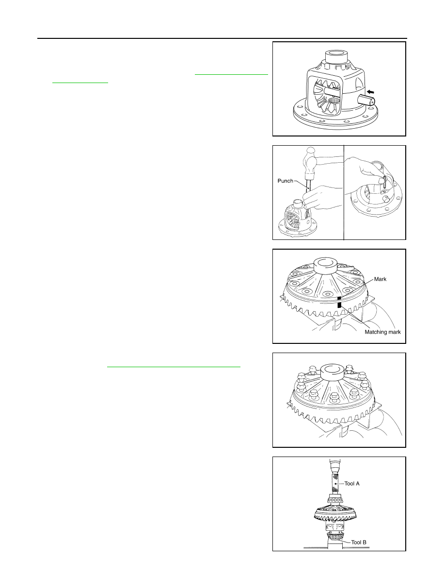
Install the pinion mate shaft and align the lock pin hole on the
pinion mate shaft with the lock pin hole on the differential case.

5.

Measure the side gear end play. If necessary, select the appro-
priate side gear thrust washers. Refer to 

DLN-364, "Inspection

and Adjustment"

.

6.

Drive a new lock pin into the pinion mate shaft until it is flush
with the differential case using suitable tool.

CAUTION:

Do not reuse lock pin.

7.

Align the matching mark of the differential case with the mark of
the drive gear, then place the drive gear onto the differential
case.

8.

Install and tighten the new drive gear bolts to the specified
torque. Refer to 

DLN-345, "Disassembly and Assembly"

.

CAUTION:

• Make sure the drive gear back and threaded holes are

clean.

• Do not reuse drive gear bolts.
• Tighten new drive gear bolts in a crisscross pattern.

9.

Press the new side bearing inner races to the differential case
using Tools.

CAUTION:

Do not reuse side bearing inner races.

SDIA0195J

SPD030

SDIA2593E

SDIA2239E

Tool number

A: KV38100300 (J-25523)

B: ST33081000 

SPD353

FRONT FINAL DRIVE

DLN-393

< DISASSEMBLY AND ASSEMBLY >

[FRONT FINAL DRIVE: M205]

C

E

F

G

H

I

J

K

L

M

A

B

DLN

N

O

P

10. Install side bearing adjusters into gear carrier.

11. Apply differential gear oil to the side bearings, and install the dif-

ferential case assembly with the side bearing outer races into
the gear carrier.

CAUTION:

Do not reuse side bearing outer race when replacing side
bearing inner race (replace as a set).

12. Install the side bearing caps with the matching marks aligned.

NOTE:
Do not tighten at this step. This allows further tightening of side
bearing adjusters.

13. Tighten each side bearing adjuster alternately turning drive gear.

14. Check and adjust tooth contact, backlash, drive gear runout and total preload torque. Refer to 

DLN-364,

"Inspection and Adjustment"

.

Recheck above items.
• After adjusting tooth contact and backlash secure side bearing

adjuster with screws and tighten side bearing cap bolt to the
specified torque. Refer to 

DLN-345, "Disassembly and Assem-

bly"

.

15. Apply multi-purpose grease to the lips of the new side oil seal. Then drive the new side oil seal in evenly to

the gear carrier using suitable tool.

CAUTION:

• Do not reuse side oil seal.
• Do not incline the new side oil seal when installing.
• Apply multi-purpose grease to the lips of the new side oil seal.

SPD527

PDIA0700E

SDIA2265E

SDIA2263E

DLN-394

< DISASSEMBLY AND ASSEMBLY >

[FRONT FINAL DRIVE: M205]

FRONT FINAL DRIVE

16. Install the extension tube with a new O-ring.

CAUTION:

• Do not reuse O-ring.
• If the extension tube is being replaced, install a new axle

shaft bearing.

17. Apply 3 mm (0.12 in) bead of sealant to the mating surface of

the carrier cover as shown.
• Use Genuine Silicone RTV or equivalent. Refer to 

GI-26,

"Recommended Chemical Products and Sealants"

.

CAUTION:

Remove any old sealant adhering to the mating surfaces.
Also remove any moisture, oil, or foreign material adhering
to the application and mating surfaces.

18. Install the carrier cover to the gear carrier. Tighten the bolts to

the specified torque. Refer to 

DLN-345, "Disassembly and

Assembly"

.

19. Install side shaft and side flange.

SDIA3205E

SDIA3204E

SERVICE DATA AND SPECIFICATIONS (SDS)

DLN-395

< SERVICE DATA AND SPECIFICATIONS (SDS) 

[FRONT FINAL DRIVE: M205]

C

E

F

G

H

I

J

K

L

M

A

B

DLN

N

O

P

SERVICE DATA AND SPECIFICATIONS (SDS)

SERVICE DATA AND SPECIFICATIONS (SDS)

General Specification

INFOID:0000000001315893

Inspection and Adjustment

INFOID:0000000001315894

DRIVE GEAR RUNOUT

Unit: mm (in)

SIDE GEAR CLEARANCE

Unit: mm (in)

PRELOAD TORQUE

Unit: N·m (kg-m, in-lb)

BACKLASH

Unit: mm (in)

COMPANION FLANGE RUNOUT

Unit: mm (in)

SELECTIVE PARTS

Drive Pinion Height Adjusting Washer

Applied model

VK56DE

Final drive model

M205

Gear ratio

2.937

Number of teeth (Drive gear/Drive pinion)

47/16

Differential gear oil capacity (Approx.)

1.6 

 (3 3/8 US pt, 2 7/8 Imp pt)

Number of pinion gears

2

Drive pinion adjustment spacer type

Collapsible

Item

Runout limit

Drive gear back face

 0.08 (0.0031) or less

Item

Specification

Side gear back clearance (Clearance between side gear and dif-
ferential case for adjusting side gear backlash)

0.20 (0.0079) or less 

(Each gear should rotate smoothly without excessive resistance 

during differential motion.)

Item

Specification

Drive pinion bearing preload torque

2.3 - 3.4 (0.23 - 0.35, 21 - 31)

Total preload torque
(Total preload torque = drive pinion bearing preload torque + side 
bearing preload torque).

2.98 - 4.76 (0.31 - 0.48, 27 - 42)

Item

Specification

Drive gear to drive pinion backlash

0.13 - 0.18 (0.0051 - 0.0071)

Item

Runout limit

Companion flange face

0.10 (0.0039) or less

Companion flange inner side

0.13 (0.0051) or less

DLN-396

< SERVICE DATA AND SPECIFICATIONS (SDS) 

[FRONT FINAL DRIVE: M205]

SERVICE DATA AND SPECIFICATIONS (SDS)

Unit: mm (in)

*Always check with the Parts Department for the latest parts information.

Side Gear Thrust Washer

Unit: mm (in)

*: Always check with the Parts Department for the latest parts information.

Thickness

Package part number*

1.22 (0.048)
1.24 (0.049)
1.27 (0.050)
1.30 (0.051)
1.32 (0.052)

38154 8S111

1.35 (0.053)
1.37 (0.054)
1.40 (0.055)
1.42 (0.056)
1.45 (0.057)

38154 8S112

1.47 (0.058)
1.50 (0.059)
1.52 (0.060)
1.55 (0.061)
1.57 (0.062)

38154 8S113

1.60 (0.063)
1.63 (0.064)
1.65 (0.065)
1.68 (0.066)
1.70 (0.067)

38154 8S114

1.73 (0.068)
1.75 (0.069)
1.78 (0.070)
1.80 (0.071)
1.83 (0.072)

38154 8S115

Thickness

Package part number*

0.76 (0.030)
0.79 (0.031)
0.81 (0.032)
0.84 (0.033)
0.87 (0.034)

38424 8S111

0.89 (0.035)
0.91 (0.036)
0.94 (0.037)
0.97 (0.038)
0.99 (0.039)

38424 8S112

PRECAUTIONS

DLN-397

< PRECAUTION >

[REAR FINAL DRIVE: R200]

C

E

F

G

H

I

J

K

L

M

A

B

DLN

N

O

P

PRECAUTION

PRECAUTIONS

Precaution for Servicing Rear Final Drive

INFOID:0000000001297284

• Before starting diagnosis of the vehicle, understand the symptoms well. Perform correct and systematic

operations. 

• Check for the correct installation status prior to removal or disassembly. When matching marks are required,

be certain they do not interfere with the function of the parts they are applied to. 

• Overhaul should be done in a clean work area, a dust proof area is recommended.
• Before disassembly, completely remove sand and mud from the exterior of the unit, preventing them from

entering into the unit during disassembly or assembly.

• Always use shop paper for cleaning the inside of components.
• Avoid using cotton gloves or a shop cloth to prevent the entering of lint.
• Check appearance of the disassembled parts for damage, deformation, and abnormal wear. Replace them

with new ones if necessary. 

• Gaskets, seals and O-rings should be replaced any time the unit is disassembled.
• Clean and flush the parts sufficiently and blow them dry.
• Be careful not to damage sliding surfaces and mating surfaces.
• When applying sealant, remove the old sealant from the mating surface; then remove any moisture, oil, and

foreign materials from the application and mating surfaces.

• In principle, tighten nuts or bolts gradually in several steps working diagonally from inside to outside. If a

tightening sequence is specified, observe it.

• During assembly, observe the specified tightening torque.
• Add new differential gear oil, petroleum jelly, or multi-purpose grease, as specified.

DLN-398

< PREPARATION >

[REAR FINAL DRIVE: R200]

PREPARATION

PREPARATION

PREPARATION

Special Service Tool

INFOID:0000000001297285

The actual shapes of Kent-Moore tools may differ from those of special service tools illustrated here.

Tool number
(Kent-Moore No.)
Tool name

Description

KV40104000
(

)

Flange wrench

Removing and installing drive pinion lock nut
a: 85 mm (3.35 in) dia.
b: 65 mm (2.56 in) dia.

KV381054S0
(J-34286)
Puller

Removing front oil seal 

ST30720000
(J-25405)
Drift

• Installing front oil seal
• Installing drive pinion rear bearing outer 

race

a: 77 mm (3.03 in) dia.
b: 55.5 mm (2.185 in) dia.

ST36230000
(J-25840-A)
Sliding hammer 

Removing side flange

KV40104100
(

)

Attachment

Removing side flange

KV38100200
(J-26233)
Drift

Installing side oil seal
a: 65 mm (2.56 in) dia.
b: 49 mm (1.93 in) dia.

NT659

ZZA0601D

ZZA0811D

ZZA0803D

ZZA0804D

ZZA1143D

PREPARATION

DLN-399

< PREPARATION >

[REAR FINAL DRIVE: R200]

C

E

F

G

H

I

J

K

L

M

A

B

DLN

N

O

P

KV38107900
(J-39352)
Protector

Installing side flange

KV38100800
(J-25604-01)
Attachment

Securing unit assembly
a: 541 mm (21.30 in)
b: 200 mm (7.87 in)

ST3127S000
(J-25765-A)
Preload gauge
1: GG91030000

(J-25765)
Torque wrench

2: HT62940000

(

)

Socket adapter (1/2

)

3: HT62900000

(

)

Socket adapter (3/8

)

Measuring drive pinion bearing preload torque 
and total preload torque

KV10111100
(J-37228)
Seal cutter

Removing carrier cover

ST3306S001
(

)

Differential side bearing puller set
1: ST33051001

(J-22888-20)
Puller

2: ST33061000

(J-8107-2)
Base

Removing and installing side bearing inner 
race
a: 28.5 mm (1.122 in) dia.
b: 38 mm (1.50 in) dia.

ST30031000
(J-22912-01)
Puller

Removing drive pinion rear bearing inner race

Tool number
(Kent-Moore No.)
Tool name

Description

S-NT129

SDIA0267E

NT124

S-NT046

NT072

ZZA0700D


Content      ..     224      225      226      227     ..