Nissan Pathfinder (2008 year). Manual - part 224


  Index      Manuals     Nissan Pathfinder (2008 year) - Service and Repair Manual


Search            copyright infringement  


Content      ..     222      223      224      225     ..


Nissan Pathfinder (2008 year). Manual - part 224


DLN-376

< REMOVAL AND INSTALLATION >

[FRONT FINAL DRIVE: M205]

FRONT FINAL DRIVE

REMOVAL AND INSTALLATION

FRONT FINAL DRIVE

Removal and Installation

INFOID:0000000001315891

REMOVAL

1.

Drain the differential gear oil. Refer to 

DLN-371

.

2.

Remove the drive shafts from the front final drive assembly. Refer to 

FAX-6, "Removal and Installation"

.

3.

Remove the front cross member.

4.

Remove the front propeller shaft from the front final drive assembly. Refer to 

DLN-308, "Removal and

Installation"

.

5.

Disconnect the vent hose from the front final drive assembly.

6.

Support the front final drive assembly using a suitable jack.
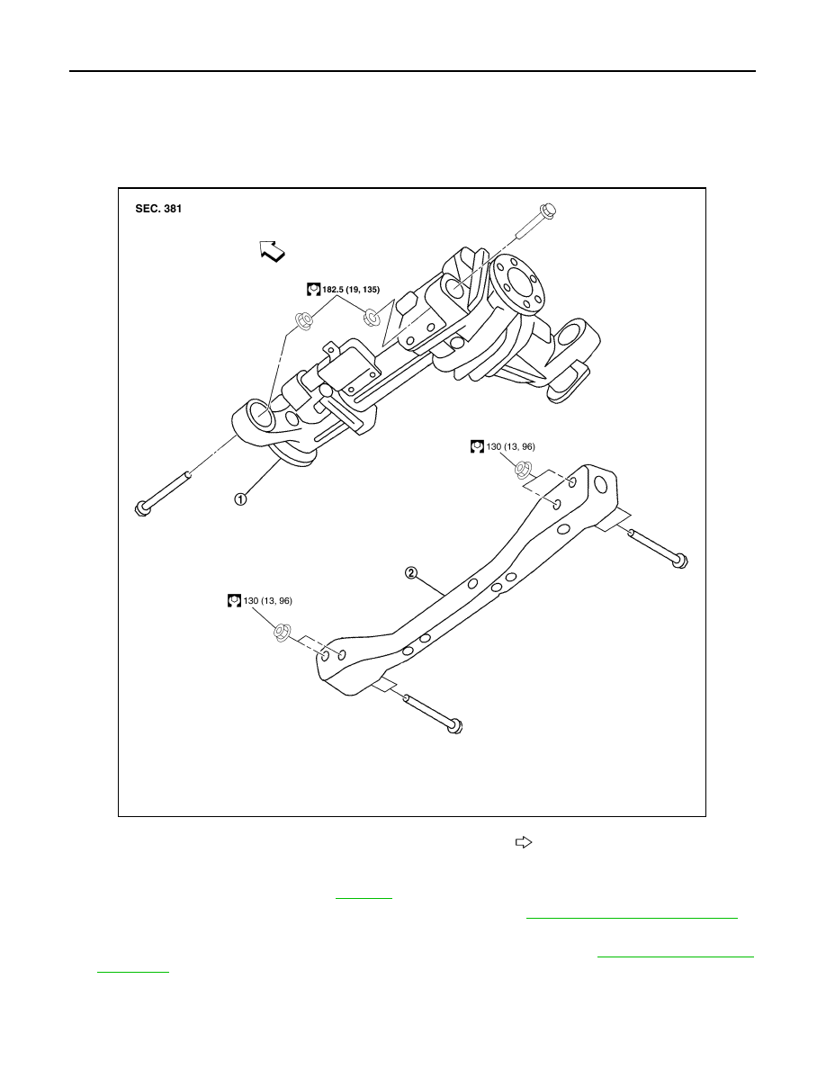
1.

Front final drive assembly

2.

Front cross member

Front

AWDIA0019GB

FRONT FINAL DRIVE

DLN-377

< REMOVAL AND INSTALLATION >

[FRONT FINAL DRIVE: M205]

C

E

F

G

H

I

J

K

L

M

A

B

DLN

N

O

P

7.

Remove the front final drive assembly bolts, then remove the
front final drive assembly.

CAUTION:

Support the front final drive assembly while removing using
a suitable jack.

INSTALLATION

Installation is in the reverse order of removal.

CAUTION:

• Make sure there are no pinched or restricted areas on the breather hose caused by folding or bend-

ing when installing it.

• Fill the front final drive assembly with differential gear oil after installation. Refer to 

DLN-371

.

BDIA0008E

DLN-378

< DISASSEMBLY AND ASSEMBLY >

[FRONT FINAL DRIVE: M205]

FRONT FINAL DRIVE

DISASSEMBLY AND ASSEMBLY

FRONT FINAL DRIVE

Disassembly and Assembly

INFOID:0000000001315892

COMPONENTS

1.

Side bearing adjuster

2.

Side bearing

3.

Side gear thrust washer

4.

Side gear

5.

Lock pin

6.

Pinion mate thrust washer

7.

Pinion mate gear

8.

Pinion mate shaft

9.

Drive pinion

10. Drive pinion height adjusting 

washer

11.

Drive pinion rear bearing

12. Collapsible spacer

13. Breather tube

14. Differential side flange

15. Dust shield

16. Circular clip

17. Side oil seal

18. Drive pinion front bearing

19. Front oil seal

20. Companion flange

21. Drive pinion lock nut

22. Drain plug

23. Differential side shaft

24. Differential side shaft bearing

25. Extension tube

26. O-ring

27. Gear carrier

AWDIA0020GB

FRONT FINAL DRIVE

DLN-379

< DISASSEMBLY AND ASSEMBLY >

[FRONT FINAL DRIVE: M205]

C

E

F

G

H

I

J

K

L

M

A

B

DLN

N

O

P

ASSEMBLY INSPECTION AND ADJUSTMENT

• Drain the differential gear oil before inspection and adjustment. Refer to 

DLN-371

.

• Remove and install the carrier cover as necessary for inspection and adjustment. Refer to 

DLN-375

.

Total Preload Torque

1.

Install the differential side shaft and differential side flange if necessary.

CAUTION:

The differential side shaft and differential side flange must be installed in order to measure total
preload torque. 

2.

Rotate the drive pinion back and forth 2 to 3 times to check for unusual noise and rotation malfunction.

3.

Rotate the drive pinion at least 20 times to check for smooth operation of the bearings.

4.

Measure total preload torque using Tool.

NOTE:
Total preload torque = Drive pinion bearing preload torque +
Side bearing preload torque

• If the measured value is out of the specification, check and adjust each part. Adjust the drive pinion

bearing preload torque first, then adjust the side bearing preload torque.

Drive Gear Runout

1.

Fit a dial indicator to the drive gear back face.

2.

Rotate the drive gear to measure runout.

• If the runout is outside of the limit, check the condition of the drive

gear assembly. Foreign material may be caught between the drive
gear and differential case, or the differential case or drive gear may
be deformed.

CAUTION:

Replace drive gear and drive pinion as a set.

Tooth Contact

28. Plate

29. Differential case

30. Drive gear

31. Side bearing cap

32. Filler plug

33. Carrier cover

34. Bushing

35. Bearing

36

Screw

37

Dowel pin

Tool number

: ST3127S000 (J-25765-A)

Total preload torque:

2.98 - 4.76 N·m (0.31 - 0.48 kg-m, 27 - 42 in-lb)

PDIA0697E

If the total preload torque is greater than specification

On drive pinion bearings:

Replace the collapsible spacer.

On side bearings:

Loosen the side bearing adjuster by the same amount on each 
side.

If the total preload torque is less than specification

On drive pinion bearings:

Tighten the drive pinion lock nut.

On side bearings:

Tighten the side bearing adjuster by the same amount on each 
side.

Runout limit:

0.08 mm (0.0031 in) or less

SPD886

DLN-380

< DISASSEMBLY AND ASSEMBLY >

[FRONT FINAL DRIVE: M205]

FRONT FINAL DRIVE

1.

Apply red lead to the drive gear.
NOTE:
Apply red lead to both faces of three to four gears, at four loca-
tions evenly spaced on the drive gear.

2.

Rotate the drive gear back and forth several times. Then check
for correct drive pinion to drive gear tooth contact as shown.

CAUTION:

Check tooth contact on drive side and reverse side.

3.

If the tooth contact is improperly adjusted, follow the procedure
below to adjust the drive pinion height (dimension X).

• If the tooth contact is near the face (face contact), or near the heel

(heel contact), use a thicker drive pinion height adjusting washer to
move drive pinion closer to the drive gear.
Refer to 

DLN-395, "Inspection and Adjustment"

.

• If the tooth contact is near the flank (flank contact), or near the toe

(toe contact), use a thinner drive pinion height adjusting washer to
move the drive pinion farther from the drive gear.
Refer to 

DLN-395, "Inspection and Adjustment"

.

SPD357

SDIA0570E

SDIA0517E

PDIA0440E

PDIA0441E

FRONT FINAL DRIVE

DLN-381

< DISASSEMBLY AND ASSEMBLY >

[FRONT FINAL DRIVE: M205]

C

E

F

G

H

I

J

K

L

M

A

B

DLN

N

O

P

Backlash

1.

Fit a dial indicator to the drive gear face to measure the back-
lash.

• If the backlash is outside of the specification, adjust each side

bearing adjuster.

CAUTION:

Do not change the side bearing adjusters by different
amounts as it will change the side bearing preload torque.

Companion Flange Runout

1.

Rotate companion flange and check for runout on the compan-
ion flange face (inner side of the bolt holes) and companion
flange inner side (socket diameter) using suitable tool.

2.

If the runout is outside the runout limit, follow the procedure
below to adjust.

a.

Rotate the companion flange on the drive pinion by 90

°

, 180

°

and 270

°

 while checking for the position where the runout is minimum.

b.

If the runout is still outside of the runout limit after the companion flange has been rotated on the drive pin-
ion, possible cause could be an assembly malfunction of drive pinion and drive pinion bearing or a mal-
functioning drive pinion bearing.

c.

If the runout is still outside of the runout limit after repair of the assembly of drive pinion and drive pinion
bearing or drive pinion bearing, replace the companion flange.

DISASSEMBLY

Differential Assembly

1.

Drain the differential gear oil if necessary.

Backlash:

0.13 - 0.18 mm (0.0051 - 0.0071 in)

SPD513

If the backlash is greater than specification:

Loosen side bearing adjuster A and tighten side bear-
ing adjuster B by the same amount.

If the backlash is less than specification:

Loosen side bearing adjuster B and tighten side bear-
ing adjuster A by the same amount.

SDIA2262E

Runout limit

Companion flange face:

0.10 mm (0.0039 in)

Companion flange inner side:

0.13 mm (0.0051 in)

SDIA2078E

DLN-382

< DISASSEMBLY AND ASSEMBLY >

[FRONT FINAL DRIVE: M205]

FRONT FINAL DRIVE

2.

Remove the differential side shaft and differential side flange
using suitable tool.

3.

Remove the extension tube and O-ring from the gear carrier.

4.

Place a small hole in the side oil seal case using suitable tool.

5.

Remove the side oil seal using Tool as shown.

6.

Remove the carrier cover bolts and separate the carrier cover
from the gear carrier using Tool.

CAUTION:

• Do not damage the mating surface.
• Do not insert flat-bladed screwdriver, this will damage the

mating surface.

BDIA0006E

SDIA3205E

LDIA0129E

Tool number

: SP8P

LDIA0130E

Tool number

: KV10111100 (J-37228)

PDIA0699E

FRONT FINAL DRIVE

DLN-383

< DISASSEMBLY AND ASSEMBLY >

[FRONT FINAL DRIVE: M205]

C

E

F

G

H

I

J

K

L

M

A

B

DLN

N

O

P

7.

For proper reinstallation, paint matching marks on one side of
the side bearing cap and gear carrier.

CAUTION:

• For matching marks, use paint. Do not damage side bear-

ing cap or gear carrier.

• Side bearing caps are line-board during manufacture. The

matching marks are used to reinstall them in their original
positions.

8.

Remove the side bearing caps.

9.

Remove the side bearing adjuster.

10. Lift the differential case assembly out of the gear carrier. 

CAUTION:

Keep side bearing outer races together with side bearing
inner races. Do not mix them up.

11. Remove side bearing inner race using Tools as shown.

CAUTION:

• Do not remove side bearing inner race unless it is being

replaced.

• Place copper plates between the vise and the side bearing

inner race and drive gear to prevent damage.

• Engage puller jaws in groove to prevent damage to bear-

ing.

PDIA0700E

PDIA0701E

SDIA2230E

SPD527

Tool number

A: ST33081000 (

)

B: ST30021000 (

)

SDIA2237E


Content      ..     222      223      224      225     ..