Nissan Pathfinder (2008 year). Manual - part 215
DLN-304
< SERVICE DATA AND SPECIFICATIONS (SDS)
[TRANSFER: TX15B]
SERVICE DATA AND SPECIFICATIONS (SDS)
SERVICE DATA AND SPECIFICATIONS (SDS)
SERVICE DATA AND SPECIFICATIONS (SDS)
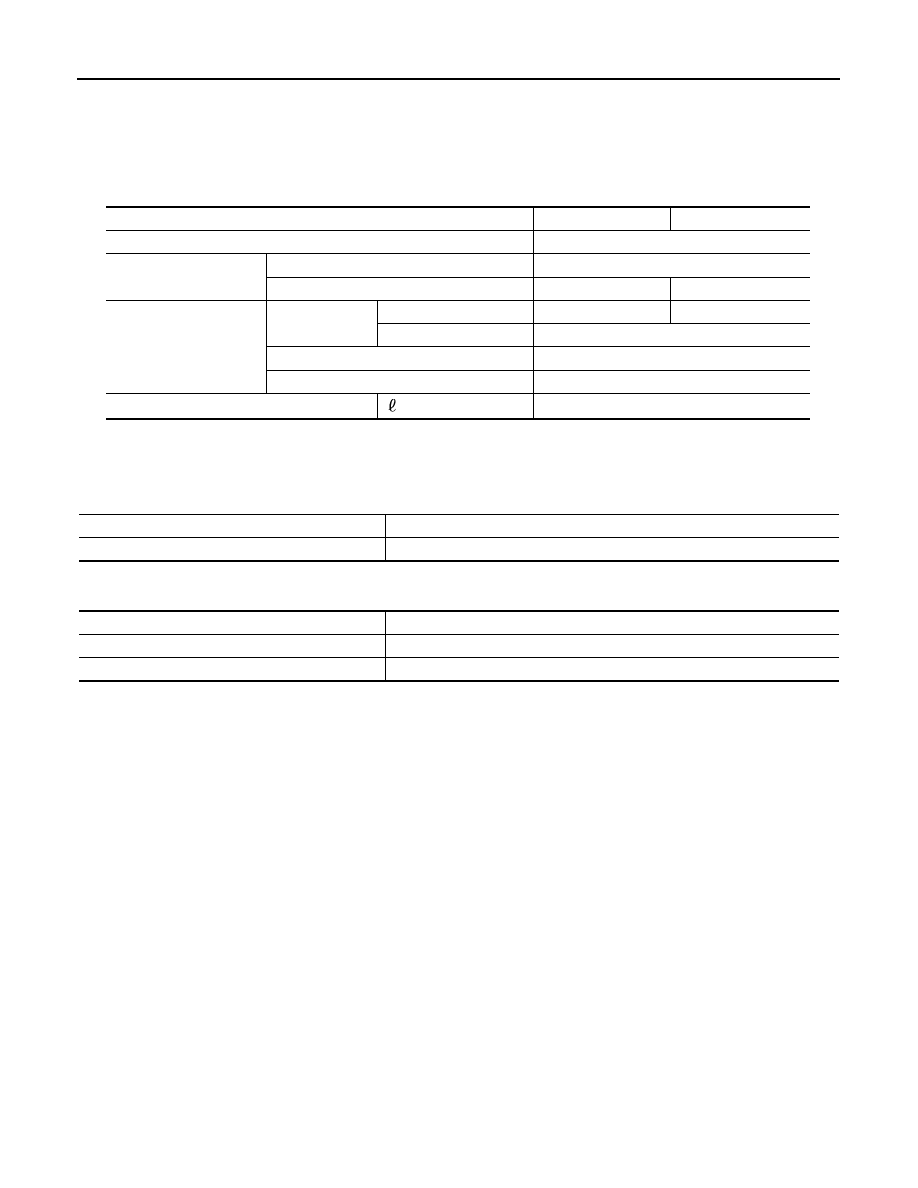
General Specification
INFOID:0000000001282325
Inspection and Adjustment
INFOID:0000000001282326
PINION GEAR END PLAY
Unit: mm (in)
CLEARANCE BETWEEN SHIFT FORK AND SLEEVE
Unit: mm (in)
Applied model
VQ40DE
VK56DE
Transfer model
TX15B
Gear ratio
High
1.000
Low
2.625
2.596
Number of teeth
Planetary gear
Sun gear
56
57
Internal gear
91
Front drive sprocket
38
Front drive shaft
38
Fluid Capacity (Approx)
(US qt, Imp qt)
2.0 (2 1/8, 1 3/4)
Item
Standard
Pinion gear end play
0.1 - 0.7 (0.004 - 0.028)
Item
Standard
2-4 shift fork to 2-4 sleeve
Less than 0.46 (0.018)
L-H shift fork to L-H sleeve
Less than 0.46 (0.018)