Nissan Pathfinder (2008 year). Manual - part 116
BRC-234
< REMOVAL AND INSTALLATION >
[HDC/HSA/VDC/TCS/ABS]
ACTUATOR AND ELECTRIC UNIT (ASSEMBLY)
ACTUATOR AND ELECTRIC UNIT (ASSEMBLY)
Removal and Installation
INFOID:0000000001297856
REMOVAL
1.
Disconnect the battery negative terminal.
2.
Drain the brake fluid. Refer to
.
3.
Disconnect the actuator harness from the ABS actuator and electric unit (control unit).
CAUTION:
• To remove the brake tubes, use a flare nut wrench to prevent the flare nuts and brake tubes from
being damaged.
• Be careful not to splash brake fluid on painted areas.
4.
Disconnect the brake tubes.
5.
Remove the three bolts and remove the ABS actuator and electric unit (control unit).
INSTALLATION
Installation is in the reverse order of removal.
CAUTION:
To install, use a flare nut wrench (commercial service tool).
• Always tighten brake tubes to specification when installing. Refer to
.
• Never reuse drained brake fluid.
• After installation of the ABS actuator and electric unit (control unit), refill brake system with new
brake fluid. Then bleed the air from the system. Refer to
.
NOTE:
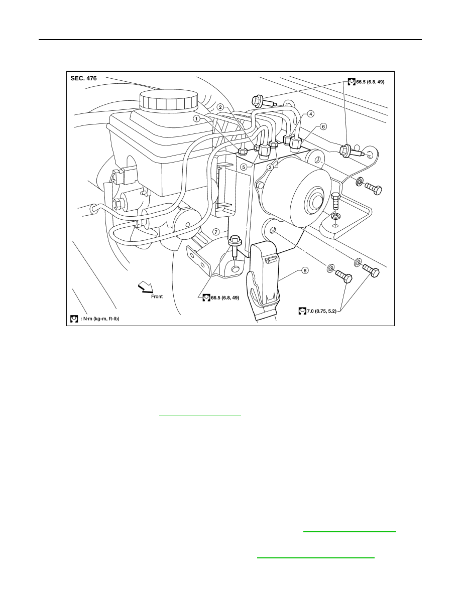
LFIA0244E
1. To rear left disc brake
2. To rear right disc brake
3. To front left disc brake
4. To front right disc brake
5. From the master cylinder secondary
side
6. From the master cylinder primary
side
7. ABS actuator and electric unit
(control unit)
8. Harness connector