Nissan Pathfinder (2008 year). Manual - part 88


  Index      Manuals     Nissan Pathfinder (2008 year) - Service and Repair Manual


Search            copyright infringement  


Content      ..     86      87      88      89     ..


Nissan Pathfinder (2008 year). Manual - part 88


BRC-10

< BASIC INSPECTION >

[VDC/TCS/ABS]

DIAGNOSIS AND REPAIR WORKFLOW

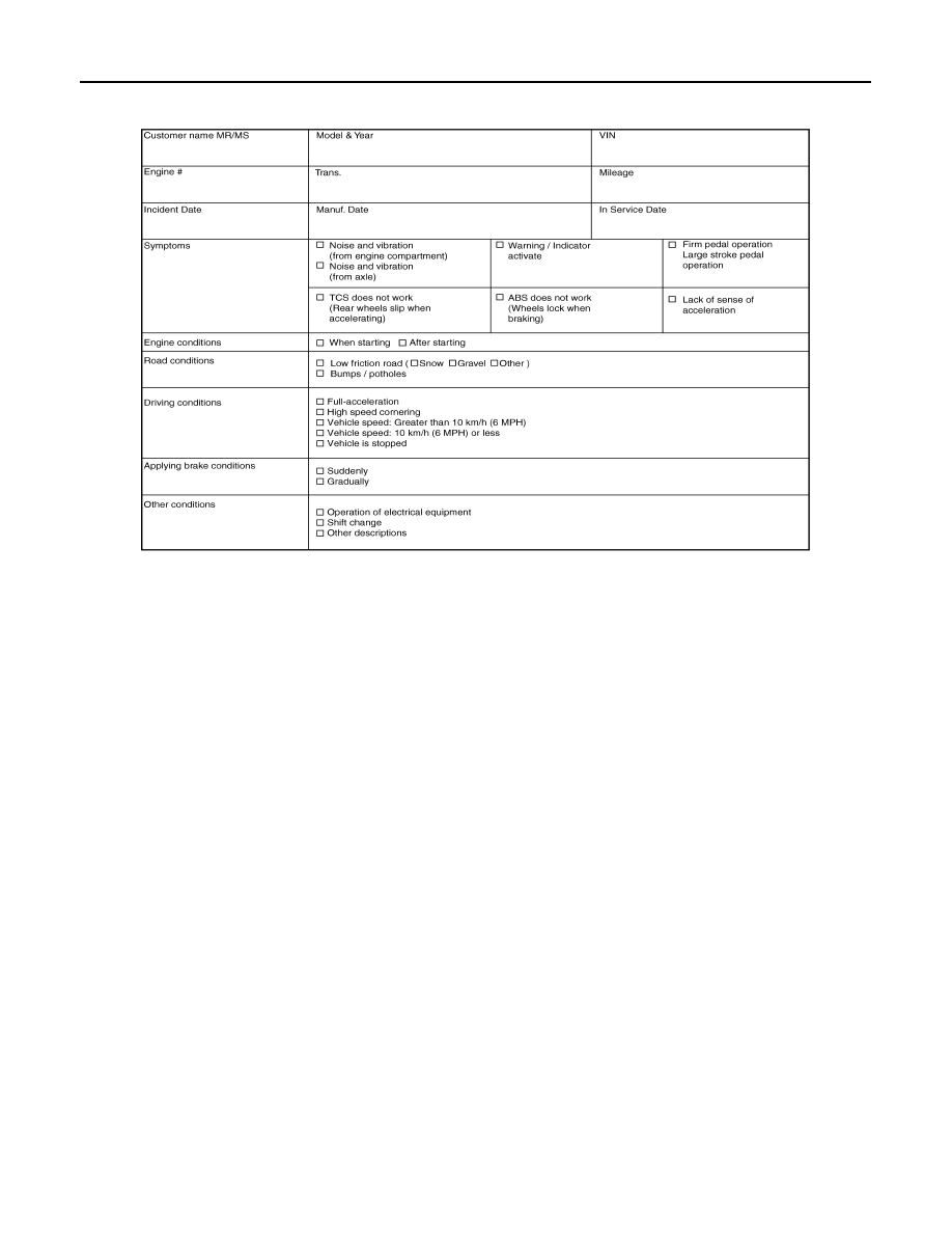
Diagnostic Work Sheet

INFOID:0000000001690791

SFIA3265E

INSPECTION AND ADJUSTMENT

BRC-11

< BASIC INSPECTION >

[VDC/TCS/ABS]

C

D

E

G

H

I

J

K

L

M

A

B

BRC

N

O

P

INSPECTION AND ADJUSTMENT

ADDITIONAL SERVICE WHEN REPLACING CONTROL UNIT

ADDITIONAL SERVICE WHEN REPLACING CONTROL UNIT : Description

INFOID:0000000001690792

After replacing the ABS actuator and electric unit (control unit), perform the following procedures:
• Neutral position adjustment for the steering angle sensor
• Calibration of the decel G sensor

ADDITIONAL SERVICE WHEN REPLACING CONTROL UNIT : Special Repair Re-
quirement

INFOID:0000000001690793

1.

PERFORM THE NEUTRAL POSITION ADJUSTMENT FOR THE STEERING ANGLE SENSOR

Perform the neutral position adjustment for the steering angle sensor.

>> Refer to 

BRC-11, "ADJUSTMENT OF STEERING ANGLE SENSOR NEUTRAL POSITION : Spe-

cial Repair Requirement"

GO TO 2

2.

PERFORM CALIBRATION OF THE DECEL G SENSOR

Perform calibration of the decel G sensor.

>> Refer to 

BRC-12, "CALIBRATION OF DECEL G SENSOR : Special Repair Requirement"

.

ADJUSTMENT OF STEERING ANGLE SENSOR NEUTRAL POSITION

ADJUSTMENT OF STEERING ANGLE SENSOR NEUTRAL POSITION : Description

INFOID:0000000001690794

Refer to the table below to determine if adjustment of steering angle sensor neutral position is required.

×

: Required –: Not required

ADJUSTMENT OF STEERING ANGLE SENSOR NEUTRAL POSITION : Special Re-
pair Requirement

INFOID:0000000001690795

ADJUSTMENT OF STEERING ANGLE SENSOR NEUTRAL POSITION

CAUTION:

To adjust neutral position of steering angle sensor, make sure to use CONSULT-III
(Adjustment cannot be done without CONSULT-III)

1.

ALIGN THE VEHICLE STATUS

Stop vehicle with front wheels in straight-ahead position.

Situation

Adjustment of steering angle sensor neutral position

Removing/Installing ABS actuator and electric unit (control unit)

Replacing ABS actuator and electric unit (control unit)

×

Removing/Installing steering angle sensor

×

Replacing steering angle sensor

×

Removing/Installing steering components

×

Replacing steering components

×

Removing/Installing suspension components

×

Replacing suspension components

×

Change tires to new ones

Tire rotation

Adjusting wheel alignment

×

BRC-12

< BASIC INSPECTION >

[VDC/TCS/ABS]

INSPECTION AND ADJUSTMENT

>> GO TO 2

2.

PERFORM THE NEUTRAL POSITION ADJUSTMENT FOR THE STEERING ANGLE SENSOR

1.

On the CONSULT-III screen, touch “WORK SUPPORT” and “ST ANG SEN ADJUSTMENT” in order.

2.

Touch “START”.

CAUTION:

Do not touch steering wheel while adjusting steering angle sensor.

3.

After approximately 10 seconds, touch “END”.
NOTE:
After approximately 60 seconds, it ends automatically.

4.

Turn ignition switch OFF, then turn it ON again.

CAUTION:

Be sure to perform above operation.

>> GO TO 3

3.

CHECK DATA MONITOR

1.

Run vehicle with front wheels in straight-ahead position, then stop.

2.

Select “DATA MONITOR”. Then make sure “STR ANGLE SIG” is within 0

±

2.5

°

.

Is the steering angle within the specified range?

YES

>> GO TO 4

NO

>> Perform the neutral position adjustment for the steering angle sensor again, GO TO 1

4.

ERASE THE SELF-DIAGNOSIS MEMORY

Erase the self-diagnosis memory of the ABS actuator and electric unit (control unit) and ECM.
• ABS actuator and electric unit (control unit): Refer to 

BRC-21, "CONSULT-III Function (ABS)"

.

• ECM: Refer to 

EC-74, "CONSULT-III Function (ENGINE)"

 (VQ40DE) or 

EC-542, "CONSULT-III Function

(ENGINE)"

 (VK56DE).

Are the memories erased?

YES

>> INSPECTION END

NO

>> Check the items indicated by the self-diagnosis.

CALIBRATION OF DECEL G SENSOR

CALIBRATION OF DECEL G SENSOR : Description

INFOID:0000000001690796

Refer to the table below to determine if calibration of the decel G sensor is required.

×

: Required –: Not required

CALIBRATION OF DECEL G SENSOR : Special Repair Requirement

INFOID:0000000001690797

CALIBRATION OF DECEL G SENSOR

CAUTION:

To calibrate the decel G sensor, make sure to use CONSULT-III

Situation

Calibration of decel G sensor

Removing/Installing ABS actuator and electric unit (control unit)

Replacing ABS actuator and electric unit (control unit)

×

Removing/Installing steering angle sensor

×

Replacing steering angle sensor

×

Removing/Installing steering components

×

Replacing steering components

×

Removing/Installing suspension components

×

Replacing suspension components

×

Change tires to new ones

Tire rotation

Adjusting wheel alignment

×

INSPECTION AND ADJUSTMENT

BRC-13

< BASIC INSPECTION >

[VDC/TCS/ABS]

C

D

E

G

H

I

J

K

L

M

A

B

BRC

N

O

P

(Calibration cannot be done without CONSULT-III)

1.

ALIGN THE VEHICLE STATUS

Stop vehicle with front wheels in straight-ahead position.

>> GO TO 2

2.

PERFORM CALIBRATION OF DECEL G SENSOR

1.

On the CONSULT-III screen, touch “WORK SUPPORT” and “DECEL G SEN CALIBRATION” in order.

2.

Touch “START”.

3.

After approximately 10 seconds, touch “END”.
NOTE:
After approximately 60 seconds, it ends automatically.

4.

Turn ignition switch OFF, then turn it ON again.

CAUTION:

Be sure to perform above operation.

>> GO TO 3

3.

CHECK DATA MONITOR

1.

Run vehicle with front wheels in straight-ahead position, then stop.

2.

Select “DATA MONITOR”. Then make sure “DECEL G SEN” is within 

±

.

Is the inspection result normal?

YES

>> GO TO 4

NO

>> Perform calibration of decel G sensor again, GO TO 1

4.

ERASE THE SELF-DIAGNOSIS MEMORY

Erase the self-diagnosis memory of the ABS actuator and electric unit (control unit) and ECM.
• ABS actuator and electric unit (control unit): Refer to 

BRC-21, "CONSULT-III Function (ABS)"

.

• ECM: Refer to 

EC-74, "CONSULT-III Function (ENGINE)"

 (VQ40DE) or 

EC-542, "CONSULT-III Function

(ENGINE)"

 (VK56DE).

Are the memories erased?

YES

>> INSPECTION END

NO

>> Check the items indicated by the self-diagnosis.

BRC-14

< FUNCTION DIAGNOSIS >

[VDC/TCS/ABS]

VDC

FUNCTION DIAGNOSIS

VDC

System Diagram

INFOID:0000000001690798

WFIA0356E

VDC

BRC-15

< FUNCTION DIAGNOSIS >

[VDC/TCS/ABS]

C

D

E

G

H

I

J

K

L

M

A

B

BRC

N

O

P

HYDRAULIC CIRCUIT DIAGRAM

System Description

INFOID:0000000001690799

• Vehicle Dynamics Control system detects driver

s steering operation amount and brake pedal travel from

steering angle sensor and pressure sensors. Using information from yaw rate/side/decel G sensor and
wheel sensor, VDC judges driving condition (conditions of under steer and over steer) to improve vehicle
driving stability by controlling brake application to 4 wheels and engine output.

• During VDC operation, it informs driver of system operation by flashing SLIP indicator lamp.
• Electrical system diagnosis by CONSULT-III is available.
• Active booster, delta stroke sensor, rear pressure sensor and stop lamp relay are available onvehicles

equipped with VK56DE only.

WFIA0357E

BRC-16

< FUNCTION DIAGNOSIS >

[VDC/TCS/ABS]

VDC

Component Parts Location

INFOID:0000000001690800

WFIA0359E

VDC

BRC-17

< FUNCTION DIAGNOSIS >

[VDC/TCS/ABS]

C

D

E

G

H

I

J

K

L

M

A

B

BRC

N

O

P

Component Description

INFOID:0000000001690801

*: With VK56DE only

Component parts

Reference

ABS actuator and electric unit (control unit)

Pump

BRC-35, "Description"

Motor

Actuator relay

BRC-53, "Description"

Solenoid valve

BRC-45, "Description"

VDC switch-over valve
(CV1, CV2, SV1, SV2)

BRC-69, "Description"

Wheel sensor

BRC-26, "Description"

Yaw rate/side/decel G sensor

BRC-37, "Description"

Steering angle sensor

BRC-58, "Description"

VDC OFF switch

BRC-79, "Description"

ABS warning lamp

BRC-81, "Description"

Brake warning lamp

BRC-82, "Description"

VDC OFF indicator lamp

BRC-83, "Description"

SLIP indicator lamp

BRC-84, "Description"

Front pressure sensor

BRC-55, "Description"

Rear pressure sensor*

Active booster*

BRC-73, "Description"

Delta stroke sensor*

BRC-76, "Description"


Content      ..     86      87      88      89     ..