Nissan Pathfinder (2008 year). Manual - part 18
AP-2
< BASIC INSPECTION >
DIAGNOSIS AND REPAIR WORKFLOW
BASIC INSPECTION
DIAGNOSIS AND REPAIR WORKFLOW
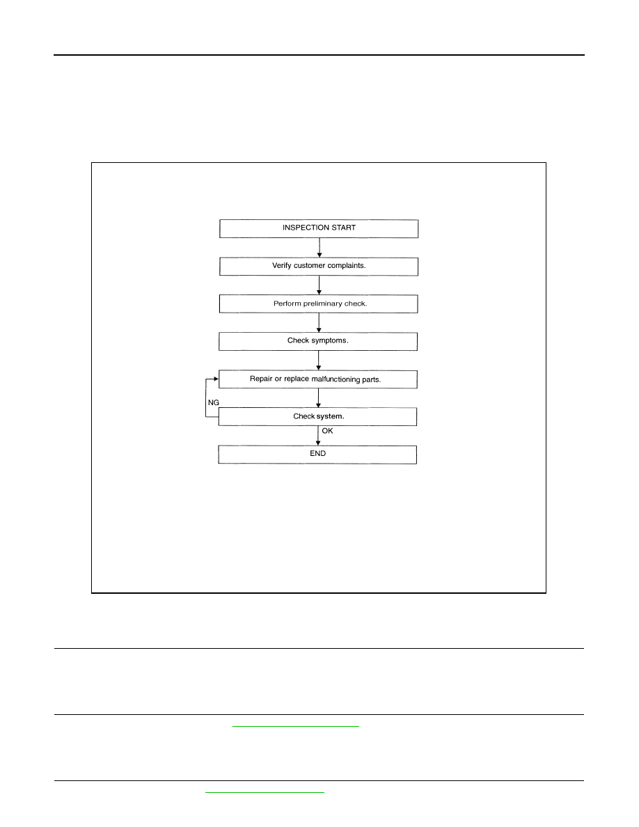
Repair Work Flow
INFOID:0000000001726708
WORK FLOW
DETAILED FLOW
1.
CUSTOMER INFORMATION
Talk to the customer to obtain detailed information about the symptom.
>> GO TO 2
2.
PRELIMINARY CHECK
Perform preliminary check. Refer to
.
>> GO TO 3
3.
SYMPTOM
Check for symptoms. Refer to
.
AWJIA0001GB