Nissan Pathfinder (2007 year). Manual - part 31


  Index      Manuals     Nissan Pathfinder (2007 year) - Service and Repair Manual


Search            copyright infringement  


Content      ..     29      30      31      32     ..


Nissan Pathfinder (2007 year). Manual - part 31


A/T SHIFT LOCK SYSTEM

AT-219

D

E

F

G

H

I

J

K

L

M

A

B

AT

2007 Pathfinder

Diagnostic Procedure

ECS00ELQ

SYMPTOM 1:

Selector lever cannot be moved from “P” position with key in ON position and brake pedal
applied.

Selector lever can be moved from “P” position with key in ON position and brake pedal released.

Selector lever can be moved from “P” position when key is removed from key cylinder.

SYMPTOM 2:

Ignition key cannot be removed when selector lever is set to “P” position.

Ignition key can be removed when selector lever is set to any position except “P”.

1. 

CHECK KEY INTERLOCK CABLE

Check key interlock cable for damage.

OK or NG

OK

>> GO TO 2.

NG

>> Repair key interlock cable. Refer to 

AT-222, "KEY INTERLOCK CABLE"

 .

2. 

CHECK SELECTOR LEVER POSITION

Check selector lever position for damage. Refer to 

AT-216, "Checking of A/T Position"

 .

OK or NG

OK

>> GO TO 3.

NG

>> Check selector lever. Refer to 

AT-216, "Adjustment of A/T Position"

 .

3. 

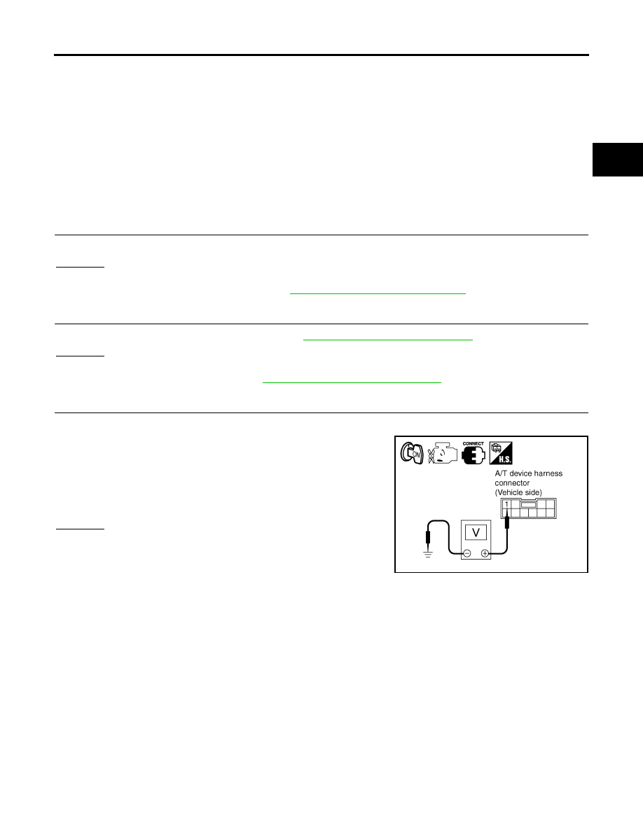
CHECK INPUT SIGNAL A/T DEVICE

1.

Turn ignition switch “ON”.

2.

Check voltage between A/T device harness connector M156 ter-
minal 1 and ground.

OK or NG

OK

>> GO TO 5.

NG

>> GO TO 4.

Voltage

Depressed brake pedal

:Battery voltage

Released brake pedal

:Approx. 0V

SCIA2122E

AT-220

A/T SHIFT LOCK SYSTEM

2007 Pathfinder

4. 

DETECT MALFUNCTIONING ITEM

Check the following.

1.

Harness for short or open between ignition switch and stop lamp switch harness connector E38 terminal
3.

2.

Harness for short or open between stop lamp switch harness connector E38 terminal 4 and A/T device
harness connector M156 terminal 1.

3.

10A fuse. [No.12, located in the fuse block (J/B)]

4.

Stop lamp switch.

Check continuity between stop lamp switch terminals 3 and 4.

Check stop lamp switch after adjusting brake pedal — refer to   

BR-6, "BRAKE PEDAL"

 .

OK or NG

OK

>> GO TO 5.

NG

>> Repair or replace damaged parts.

5. 

CHECK GROUND CIRCUIT

1.

Turn ignition switch “OFF”.

2.

Disconnect A/T device harness connector.

3.

Check continuity between A/T device harness connector M156
terminal 2 and ground.

If OK, check harness for short to ground and short to power.

OK or NG

OK

>> GO TO 6.

NG

>> Repair open circuit or short to ground or short to power

in harness or connectors.

SCIA3953E

Continuity should exist.

SCIA6266E

A/T SHIFT LOCK SYSTEM

AT-221

D

E

F

G

H

I

J

K

L

M

A

B

AT

2007 Pathfinder

6. 

CHECK PARK POSITION SWITCH AND SHIFT LOCK SOLENOID CIRCUIT

Check continuity between A/T device terminals 1 and 2.

OK or NG

OK

>> INSPECTION END

NG

>>

Replace park position switch or shift lock solenoid.

Repair open circuit or short to ground or short to power in harness or connectors.

SCIA6267E

AT-222

KEY INTERLOCK CABLE

2007 Pathfinder

KEY INTERLOCK CABLE

PFP:34908

Components

ECS00ELR

CAUTION:

Install key interlock cable in such a way that it will not be damaged by sharp bends, twists or inter-
ference with adjacent parts.

After installing key interlock cable to control device, make sure that casing cap and bracket are
firmly secured in their positions. If casing cap can be removed with an external load of less than
39 N (4.0 kg, 8.8 lb), replace key interlock cable with new one.

WCIA0467E

KEY INTERLOCK CABLE

AT-223

D

E

F

G

H

I

J

K

L

M

A

B

AT

2007 Pathfinder

Removal and Installation

ECS00ELS

REMOVAL

1.

Unlock slider from adjuster holder by squeezing lock tabs.

2.

Remove casing cap from bracket of control device assembly
and remove interlock rod from adjuster holder.

3.

Remove holder from key cylinder and remove key interlock
cable.

SCIA1230E

LCIA0375E

AT-224

KEY INTERLOCK CABLE

2007 Pathfinder

INSTALLATION

1.

Set key interlock cable to key cylinder and install holder.

2.

Turn ignition key to "LOCK" position.

3.

Set selector lever to “P” position.

4.

Insert interlock rod into adjuster holder.

5.

Install casing cap to bracket.

6.

Move slider in order to secure adjuster holder to interlock rod.

SCIA2258E

SCIA1232E

ON-VEHICLE SERVICE

AT-225

D

E

F

G

H

I

J

K

L

M

A

B

AT

2007 Pathfinder

ON-VEHICLE SERVICE

PFP:00000

Oil Pan

ECS00ELT

REMOVAL AND INSTALLATION
Removal

1.

Drain A/T fluid. Refer to 

AT-12, "A/T FLUID"

 .

2.

Remove oil pan and gasket.

3.

Check for foreign materials in oil pan to help determine cause of malfunction. If the A/T fluid is very dark,
has some burned smell, or contains foreign particles then friction material (clutches, band) may need
replacement. A tacky film that will not wipe clean indicates varnish build up. Varnish can cause valves,
servo, and clutches to stick and can inhibit pump pressure.

CAUTION:

If friction material is detected, flush the transmission cooler after repair. Refer to 

AT-15, "A/T Fluid

Cooler Cleaning"

 .

4.

Remove magnets from oil pan.

Installation

1.

Install the oil pan magnets as shown.

SCIA2308E

SCIA5200E

SCIA5200E

AT-226

ON-VEHICLE SERVICE

2007 Pathfinder

2.

Install the oil pan and new oil pan gasket.

CAUTION:

Be sure the oil drain plug is located to the rear of the
transmission assembly.

Before installing oil pan bolts, remove any traces of old
sealant from the sealing surfaces and threaded holes.

Do not reuse old gasket, replace with a new one.

Always replace the oil pan bolts as they are self-sealing.

Partially install the oil pan bolts in a criss-cross pattern to
prevent dislocation of the gasket.

3.

Tighten oil pan bolts in numerical order as shown.

4.

Install drain plug with new gasket to oil pan and tighten to specification.

CAUTION:

Do not reuse drain plug gasket.

5.

Refill the A/T with fluid and check for fluid leakage. Refer to 

AT-12, "A/T FLUID"

 .

SCIA2308E

Oil pan bolts

: 7.9 N·m (0.81 kg-m, 70 in-lb)

SCIA4113E

Drain plug

: 34 N·m (3.5 kg-m, 25 ft-lb)


Content      ..     29      30      31      32     ..