Nissan Pathfinder (2005 year). Manual - part 161
TROUBLE DIAGNOSIS
EC-139
C
D
E
F
G
H
I
J
K
L
M
A
EC
2005 Pathfinder
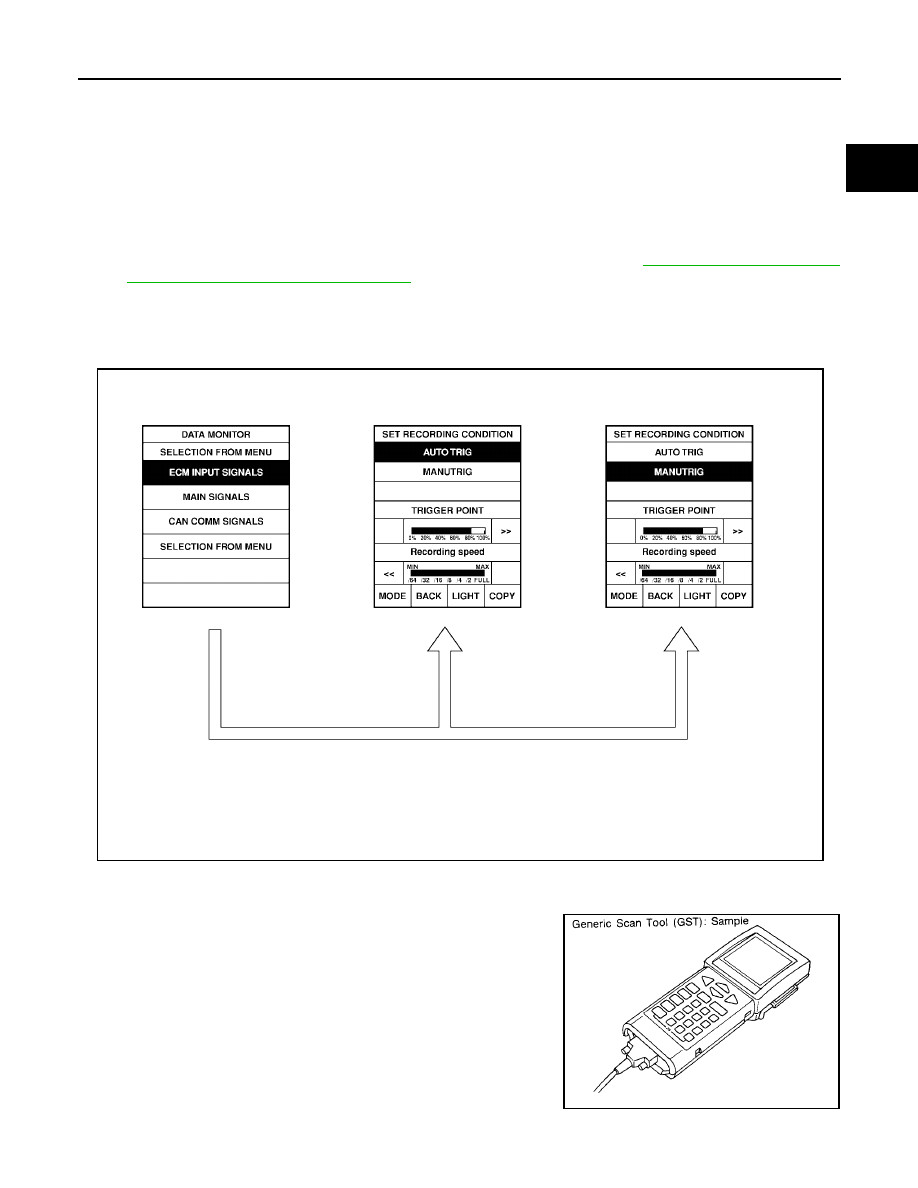
Operation
1.
“AUTO TRIG”
●
While trying to detect the DTC/1st trip DTC by performing the DTC Confirmation Procedure, be sure to
select to “DATA MONITOR (AUTO TRIG)” mode. You can confirm the malfunction at the moment it is
detected.
●
While narrowing down the possible causes, CONSULT-II should be set in “DATA MONITOR (AUTO
TRIG)” mode, especially in case the incident is intermittent.
When you are inspecting the circuit by gently shaking (or twisting) the suspicious connectors, compo-
nents and harness in the DTC Confirmation Procedure, the moment a malfunction is found the DTC/1st
trip DTC will be displayed. (Refer to “INCIDENT SIMULATION TESTS” in
cient Diagnosis for an Electrical Incident"
.)
2.
“MANU TRIG”
●
If the malfunction is displayed as soon as “DATA MONITOR” is selected, reset CONSULT-II to “MANU
TRIG”. By selecting “MANU TRIG” you can monitor and store the data. The data can be utilized for fur-
ther diagnosis, such as a comparison with the value for the normal operating condition.
Generic Scan Tool (GST) Function
UBS00K4D
DESCRIPTION
Generic Scan Tool (OBDII scan tool) complying with SAE J1978 has
8 different functions explained below.
ISO9141 is used as the protocol.
The name GST or Generic Scan Tool is used in this service manual.
PBIB0197E
SEF139P