Nissan Pathfinder. Manual - part 981
POWER SUPPLY AND GROUND CIRCUIT
RF-29
< DTC/CIRCUIT DIAGNOSIS >
C
D
E
F
G
H
I
J
L
M
A
B
RF
N
O
P
YES
>> GO TO 7.
NO
>> Repair or replace harness.
7.
CHECK MOONROOF SWITCH GROUND CIRCUIT
1. Connect moonroof motor assembly.
2. Check continuity between the moonroof switch connector and ground.
Is the inspection result normal?
YES
>> Refer to
.
NO
>> Repair or replace harness.
8.
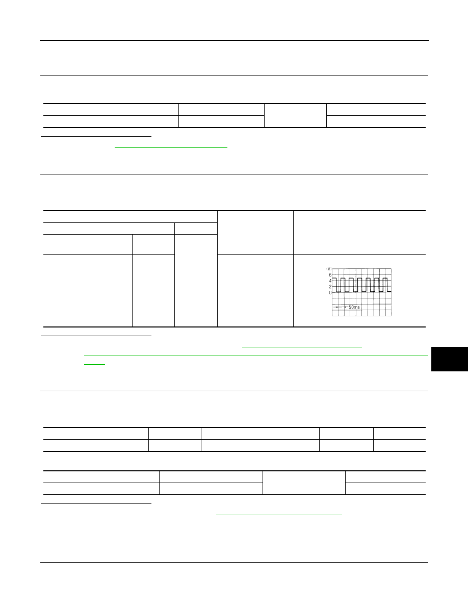
CHECK COMBINATION METER SIGNAL
1. Connect the moonroof motor assembly connector.
2. Turn ignition switch ON.
3. Check the signal between the moonroof motor assembly connector and ground with oscilloscope.
Is the inspection result normal?
YES
>> Replace moonroof motor assembly. Refer to
RF-55, "Removal and Installation"
. After that, refer to
RF-25, "ADDITIONAL SERVICE WHEN REPLACING CONTROL UNIT : Special Repair Require-
NO
>> GO TO 9.
9.
CHECK COMBINATION METER CIRCUIT
1. Turn ignition switch OFF.
2. Disconnect combination meter.
3. Check continuity between the combination meter connector and the moonroof motor assembly connector.
4. Check continuity between the combination meter connector and ground.
Is the inspection result normal?
YES
>> Replace combination meter. Refer to
MWI-82, "Removal and Installation"
NO
>> Repair or replace harness.
MOONROOF MOTOR ASSEMBLY : Special Repair Requirement
INFOID:0000000009176293
1.
PERFORM INITIALIZATION PROCEDURE
Perform the initialization procedure.
Moonroof switch connector
Terminal
Ground
Continuity
R108
6
Yes
Terminals
Condition
Signal
(Reference value)
(+)
(-)
Moonroof motor assembly
connector
Terminal
Ground
R4
8
Speedometer operated
[When vehicle speed is
approx.40km/h
(25MPH)]
ELF1080D
Combination meter connector
Terminal
Moonroof motor assembly connector
Terminal
Continuity
M24
33
R4
8
Yes
Combination meter connector
Terminal
Ground
Continuity
M24
33
No