Nissan Pathfinder. Manual - part 879


  Index      Nissan     Nissan Pathfinder (2014 year) - Service and Repair Manual


Search            


Content   ..  877  878  879  880   ..


Nissan Pathfinder. Manual - part 879


PB-4

< PERIODIC MAINTENANCE >

PARKING BRAKE SYSTEM

PERIODIC MAINTENANCE

PARKING BRAKE SYSTEM

Inspection and Adjustment

INFOID:0000000009177217

INSPECTION

Pedal Stroke

1. Operate the parking brake pedal with a force of 196 N (20.0 kg-f, 44.1 lb-f). Check that the pedal stroke is

within the specified number of notches. (Check it by listening to the clicks of the ratchet.)

2. When brake warning lamp turns ON, check that the pedal stroke is within the specified number of

notches. (Check it by listening to the clicks of the ratchet.)

Inspect Components

• Check each component for installation condition such as looseness.

• Check the parking brake pedal assembly for bend, damage and cracks. Replace if necessary.

• Check the cables for wear, damage and cracks. Replace if necessary.

• Check the parking brake switch, and replace it if necessary. Refer to 

PB-7, "Removal and Installation"

.

ADJUSTMENT

1. Secure the disc rotor using wheel nuts.
2. Remove fuse block lid. Refer to 

IP-14, "Exploded View"

.

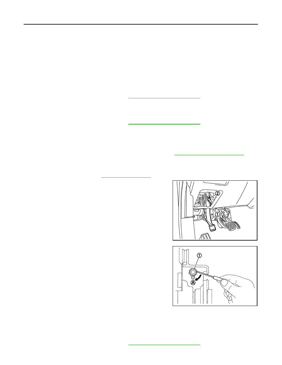
3. Release the parking brake pedal (1) by turning the adjusting nut

(2) with a deep socket wrench and loosening the cable.

4. Remove the adjusting hole plug from the disc rotor. Turn the

adjuster (1) in the direction (A) as shown using a suitable tool

until the disc rotor is locked. 

5. Turn back the adjuster 5 or 6 notches from the locked position.
6. Rotate the disc rotor to check that there is no drag. Install the

adjusting hole plug.

7. Adjust the cable with the following procedure.
a. Operate the parking brake pedal with a force of 490 N (50.0 kg-f,

110.2 lb-f) for more than 30 minutes. 

b. Adjust the parking brake pedal stroke by turning the adjusting

nut with a deep socket wrench.

CAUTION:

Do not reuse the adjusting nut if the nut is removed.

c.

Operate the parking brake pedal with a force of 196 N (20.0 kg-f, 44.1 lb-f). Check that the pedal stroke is

within the specified number of notches. (Check it by listening to the clicks of the ratchet.)

Number of notches

: Refer to 

PB-12, "Parking Brake Control"

.

Number of notches

: Refer to 

PB-12, "Parking Brake Control"

.

JPFIB0044ZZ

Number of notches

: Refer to 

PB-12, "Parking Brake Control"

.

JPFIB0002ZZ

PARKING BRAKE SYSTEM

PB-5

< PERIODIC MAINTENANCE >

C

D

E

G

H

I

J

K

L

M

A

B

PB

N

O

P

d. Rotate the disc rotor with the parking brake pedal released and check that there is no drag.

CAUTION:

If any drag is found, verify the parking brake components are installed and adjusted correctly.

PB-6

< PERIODIC MAINTENANCE >

PARKING BRAKE SHOE

PARKING BRAKE SHOE

Adjustment

INFOID:0000000009177218

1. Adjust parking brake pedal stroke. Refer to 

PB-4, "Inspection and Adjustment"

.

2. Perform parking brake break-in (drag on) operation by driving vehicle under the following conditions: 

• Drive  forward

• Vehicle speed: Approx. 40 km/h (25 MPH) set (constant and forward)

• Parking brake operating force: Approx. 160 +49.0, -0 N (16.3 +5, -0 kg-f, 36.0 +11, -0 lb-f)

• Time: Approx. 5 +5, -0 seconds.

CAUTION:

To prevent lining from getting too hot, allow a cool off period of approximately 5 minutes after

every break-in operation.

3. After the break-in procedure, check parking pedal stroke of parking brake.

CAUTION:

If it is out of the specification, adjust again. Refer to 

PB-4, "Inspection and Adjustment"

.

PARKING BRAKE CONTROL

PB-7

< REMOVAL AND INSTALLATION >

C

D

E

G

H

I

J

K

L

M

A

B

PB

N

O

P

REMOVAL AND INSTALLATION

PARKING BRAKE CONTROL

Exploded View

INFOID:0000000009177219

Removal and Installation

INFOID:0000000009177220

REMOVAL

1. Disconnect the negative and positive battery terminals, then wait at least three minutes. Refer to 

PG-90,

"Removal and Installation"

.

2. Remove lower instrument panel LH. 

IP-25, "Removal and Installation"

.

3. Disconnect parking brake switch harness connector.
4. Remove parking brake pedal assembly nuts and lower parking brake pedal assembly.
5. Remove adjusting nut and front cable from parking brake pedal assembly.
6. Remove front floor duct RH. Refer to 

VTL-11, "FRONT FLOOR DUCT : Removal and Installation - Front

Floor Duct"

.

7. Remove center blower unit. Refer to 

VTL-20, "REAR BLOWER MOTOR 1 UNIT ASSEMBLY : Removal

and Installation"

.

8. Separate front cable from rear cable and remove front cable and return spring.
9. Remove parking brake shoe and remove rear cable from toggle lever. Refer to 

PB-9, "Removal and Instal-

lation"

.

10. Remove rear cable bolts, nuts, and rear cable from vehicle.

INSTALLATION

Installation is in the reverse order of removal.

1.

Rear cable (RH)

2.

Rear cable (LH)

3.

Front cable

4.

Parking brake pedal assembly

5.

Park brake switch

6.

Adjusting nut

7.

Return spring

8.

Pin

AWFIA1030ZZ


Content   ..  877  878  879  880   ..