Nissan Pathfinder. Manual - part 770


  Index      Nissan     Nissan Pathfinder (2014 year) - Service and Repair Manual


Search            


Content   ..  768  769  770  771   ..


Nissan Pathfinder. Manual - part 770


LAN

SYSTEM

LAN-33

< SYSTEM DESCRIPTION >

[CAN]

C

D

E

F

G

H

I

J

K

L

B

A

O

P

N

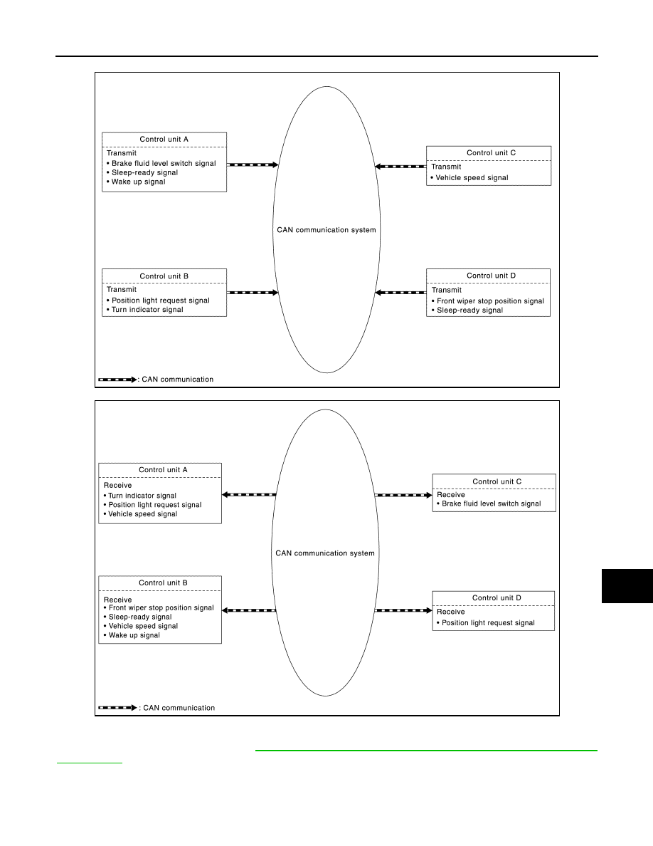
• Example: Transmitted signals

• Example: Received signals

NOTE:

The above signal names and signal communications are provided for reference purposes. For CAN communi-

cations signals of this vehicle, refer to 

LAN-36, "CAN COMMUNICATION SYSTEM : CAN Communication

Signal Chart"

.

JSMIA0576GB

JSMIA0577GB

LAN-34

< SYSTEM DESCRIPTION >

[CAN]

SYSTEM

CAN COMMUNICATION SYSTEM : CAN Communication Control Circuit

INFOID:0000000009174943

CAN communication control circuit is incorporated into the control unit and transmits/receives CAN communi-

cation signals.

*: These are the only control units wired with both ends of CAN communication system.

CAN COMMUNICATION SYSTEM : CAN System Specification Chart

INFOID:0000000009174944

Determine CAN system type from the following specification chart.

NOTE:

Refer to 

LAN-20, "Trouble Diagnosis Procedure"

 for how to use CAN system specification chart.

JSMIA0453GB

Component

System description

CAN controller

It controls CAN communication signal transmission and reception, error detection, etc.

Transceiver IC

It converts digital signal into CAN communication signal, and CAN communication signal into digital 
signal.

Noise filter

It eliminates noise of CAN communication signal.

Termination circuit

*

(Resistance of approx. 120 

Ω)

Generates a potential difference between CAN-H and CAN-L.

Body type

Wagon

Axle

2WD

4WD

Engine

VQ35DE

Transmission

CVT

Brake control

VDC

Color display

×

×

×

×

×

×

×

Around view monitor

×

×

Automatic back door system

×

×

×

×

×

Automatic drive positioner

×

×

×

×

CAN  system  type

1

2

3

4

5

6

7

8

9

CAN communication control unit

ECM

×

×

×

×

×

×

×

×

×

IPDM E/R

×

×

×

×

×

×

×

×

×

TCM

×

×

×

×

×

×

×

×

×

ABS actuator and electric unit (con-
trol unit)

×

×

×

×

×

×

×

×

×

LAN

SYSTEM

LAN-35

< SYSTEM DESCRIPTION >

[CAN]

C

D

E

F

G

H

I

J

K

L

B

A

O

P

N

×: Applicable

VEHICLE EQUIPMENT IDENTIFICATION INFORMATION

NOTE:

Check CAN system type from the vehicle shape and equipment.

Power steering control module

×

×

×

×

×

×

×

×

×

Air bag diagnosis sensor unit

×

×

×

×

×

×

×

×

×

AV control unit

×

×

×

×

×

×

×

Data link connector

×

×

×

×

×

×

×

×

×

A/C auto amp.

×

×

×

×

×

×

×

×

×

Combination meter

×

×

×

×

×

×

×

×

×

Sonar control unit

×

×

×

×

×

×

×

Steering angle sensor

×

×

×

×

×

×

×

×

×

CAN gateway

×

×

BCM

×

×

×

×

×

×

×

×

×

Around view monitor control unit

×

×

Driver seat control unit

×

×

×

×

4WD control unit

×

×

×

×

×

Automatic back door control module

×

×

×

×

×

Body type

Wagon

Axle

2WD

4WD

Engine

VQ35DE

Transmission

CVT

Brake control

VDC

Color display

×

×

×

×

×

×

×

Around view monitor

×

×

Automatic back door system

×

×

×

×

×

Automatic drive positioner

×

×

×

×

CAN  system  type

1

2

3

4

5

6

7

8

9

CAN communication control unit

LAN-36

< SYSTEM DESCRIPTION >

[CAN]

SYSTEM

CAN COMMUNICATION SYSTEM : CAN Communication Signal Chart

INFOID:0000000009174945

Refer to 

LAN-19, "How to Use CAN Communication Signal Chart"

 for how to use CAN communication signal

chart.

NOTE:

Refer to 

LAN-25, "Abbreviation List"

 for the abbreviations of the connecting units. 

T: Transmit R: Receive

Color display

Automatic back door switch

Camera switch

Seat memory switches

With color display

With automatic back door system

With around view monitor

With automatic drive positioner

ALMIA0588ZZ

Signal name

ECM

IPDM-E

TCM

AB

S

EP

S

AV

HV

A

C

M&A

STRG

SONAR

CGW

BCM

AV

M

ADP

4W

D

PWBD

A/C compressor request signal

T

R

Accelerator pedal position signal

T

R

R

R

ASCD operation signal

T

R

ASCD status signal

T

R

Closed throttle position signal

T

Cooling fan speed request signal

T

R

Engine and CVT integrated control 
signal

T

R

R

T

Engine coolant temperature signal

T

R

R

Engine speed signal

T

R

R

R

R

Engine status signal

T

R

R

R

R

Fuel consumption monitor signal

T

R

R


Content   ..  768  769  770  771   ..