Nissan Pathfinder. Manual - part 758


  Index      Nissan     Nissan Pathfinder (2014 year) - Service and Repair Manual


Search            


Content   ..  756  757  758  759   ..


Nissan Pathfinder. Manual - part 758


INSTRUMENT PANEL ASSEMBLY

IP-15

< REMOVAL AND INSTALLATION >

C

D

E

F

G

H

I

K

L

M

A

B

IP

N

O

P

Removal and Installation

INFOID:0000000009176440

CAUTION:

• Be careful not to scratch instrument panel pad and other parts.

• Whenever a suitable tool is used, always wrap a cloth around the end of the tool to protect compo-

nents from damage.

• Before servicing, turn ignition switch OFF, disconnect both battery terminals and wait at least three

minutes. 

REMOVAL

1. Disconnect the negative and positive battery terminals, then wait at least three minutes. Refer to 

PG-90,

"Removal and Installation"

.

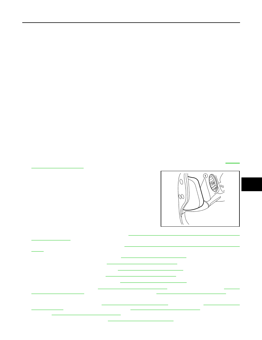
2. Remove instrument side finishers (LH/RH) (1) using a suitable

tool.

NOTE:

LH side shown; RH side similar.

3. Remove front kicking plates (LH/RH). Refer to 

INT-22, "KICKING PLATE : Removal and Installation -

Front Kicking Plate"

.

4. Remove front pillar finishers (LH/RH). Refer to 

INT-19, "FRONT PILLAR FINISHER : Removal and Instal-

lation"

.

5. Remove instrument lower panel LH. Refer to 

IP-25, "Removal and Installation"

.

6. Remove combination switch. Refer to 

BCS-81, "Removal and Installation"

.

7. Remove center console assembly. Refer to 

IP-18, "Removal and Installation"

.

8. Remove combination meter. Refer to 

MWI-82, "Removal and Installation"

.

9. Remove audio unit (BASE AUDIO). Refer to 

AV-46, "Removal and Installation"

.

10. Remove AV control unit. Refer to 

AV-365, "Removal and Installation"

 (MID AUDIO WITH BOSE), 

AV-187,

"Removal and Installation"

 (MID AUDIO WITHOUT BOSE) or 

AV-611, "Removal and Installation"

 (PRE-

MIUM AUDIO WITH NAVIGATION).

11. Remove front display unit. Refer to 

AV-49, "Removal and Installation"

 (BASE AUDIO),  

AV-191, "Removal

and Installation"

 (MID AUDIO WITHOUT BOSE), 

AV-369, "Removal and Installation"

 (MID AUDIO WITH

BOSE) or 

AV-615, "Removal and Installation"

 (PREMIUM AUDIO WITH NAVIGATION).

12. Remove glove box assembly. Refer to 

IP-26, "Removal and Installation"

.

13. Remove instrument panel tweeter grilles (LH/RH) and center speaker grille.

1.

Instrument panel assembly

2.

Center speaker grille

3.

Sunload sensor

4.

Instrument panel tweeter grille (LH)

5.

Side defroster grille (LH)

6.

Side ventilator grille (LH)

7.

Instrument side finisher (LH)

8.

Combination meter

9.

Illumination control switch

10. Trip computer switch

11. Cluster lid A

12. Steering column upper cover

13. Steering column upper cover

14. Upper switch carrier

15. Lower switch carrier

16. Fuse block cover

17. Instrument lower panel LH

18. A/C and AV switch assembly (with-

out navigation)

19. A/C and AV switch assembly finisher 

(without navigation)

20. Cluster lid C lower

21. A/C and AV switch assembly (with 

navigation)

22. Hazard switch

23. Cluster lid C

24. Front passenger air bag off indicator

25. Center ventilator grille (LH)

26. Cluster lid D

27. Center ventilator grille (RH)

28. Glove box lid

29. Glove box

30. Glove box tray

31. Glove box dampener

32. Instrument side finisher (RH)

33. Side ventilator grille (RH)

34. Side defroster grille (RH)

35. Insturment panel tweeter grille (RH) 36. Optical sensor

ALJIA0335ZZ

IP-16

< REMOVAL AND INSTALLATION >

INSTRUMENT PANEL ASSEMBLY

14. Remove instrument panel bolt (A) from the instrument panel

tweeter grille (RH) area.

15. Remove front passenger air bag module. Refer to 

SR-18, "Removal and Installation"

.

16. Remove instrument panel assembly screws.
17. Disconnect the harness connectors from the instrument panel assembly.
18. Disconnect the antenna cable.
19. Remove the instrument panel assembly.

INSTALLATION

Installation is in the reverse order of removal.

• If replacing the instrument panel, transfer all the necessary parts to the new instrument panel. 

ALJIA0776ZZ

STEERING COLUMN COVERS

IP-17

< REMOVAL AND INSTALLATION >

C

D

E

F

G

H

I

K

L

M

A

B

IP

N

O

P

STEERING COLUMN COVERS

Removal and Installation

INFOID:0000000009176441

REMOVAL

1. Remove instrument lower panel LH. Refer to 

IP-25, "Removal and Installation"

.

2. Remove steering column cover screw finishers (1) using a suit-

able tool, then remove screws.

NOTE:

Rotate steering wheel to access steering column cover screw

finishers (1) and screws (if necessary).

3. Remove steering column upper cover (2).
4. Remove steering column lower cover screw, then remove  steer-

ing column lower cover (3).

INSTALLATION

Installation is in the reverse order of removal.

ALJIA0456ZZ

IP-18

< REMOVAL AND INSTALLATION >

CENTER CONSOLE ASSEMBLY

CENTER CONSOLE ASSEMBLY 

Exploded View

INFOID:0000000009176442

Removal and Installation

INFOID:0000000009176443

REMOVAL

CAUTION:

Be careful not to scratch center console finishers and other parts.

1.

Drive mode selector switch

2.

Shift selector finisher

3.

Front seat climate control switch 
(RH) (if equipped)

4.

Front seat climate control switch 
(LH) (if equipped)

5.

Center console switch bracket

6.

Center console assembly

7.

Front console mat

8.

Front console tray

9.

Power socket

10. Center console side finisher (RH) 11. Center console side finisher (LH)

12. Center console brace

13. Center console lower brace

14. Rear center ventilator duct

15. 2nd row heated seat switch (RH) 

(if equipped)

16. 2nd row heated seat switch (LH) 

(if equipped)

17. Rear auxiliary input jack

18. Center console rear finisher lower 

bracket

19. Intelligent Key antenna

20. Center console rear finisher

21. Power socket

22. AC 120V outlet

23. Center console rear finisher upper 

bracket

24. Rear blower control

25. Rear center ventilator grille as-

sembly

26. Center console bin

27. Center console bin lid

28. Center console rear brace finsher

AWJIA1155ZZ


Content   ..  756  757  758  759   ..