Nissan Pathfinder. Manual - part 740
POWER SUPPLY AND GROUND CIRCUIT
INL-47
< DTC/CIRCUIT DIAGNOSIS >
C
D
E
F
G
H
I
J
K
M
A
B
INL
N
O
P
DTC/CIRCUIT DIAGNOSIS
POWER SUPPLY AND GROUND CIRCUIT
BCM
BCM : Diagnosis Procedure
INFOID:0000000009764027
Regarding Wiring Diagram information, refer to
.
1.
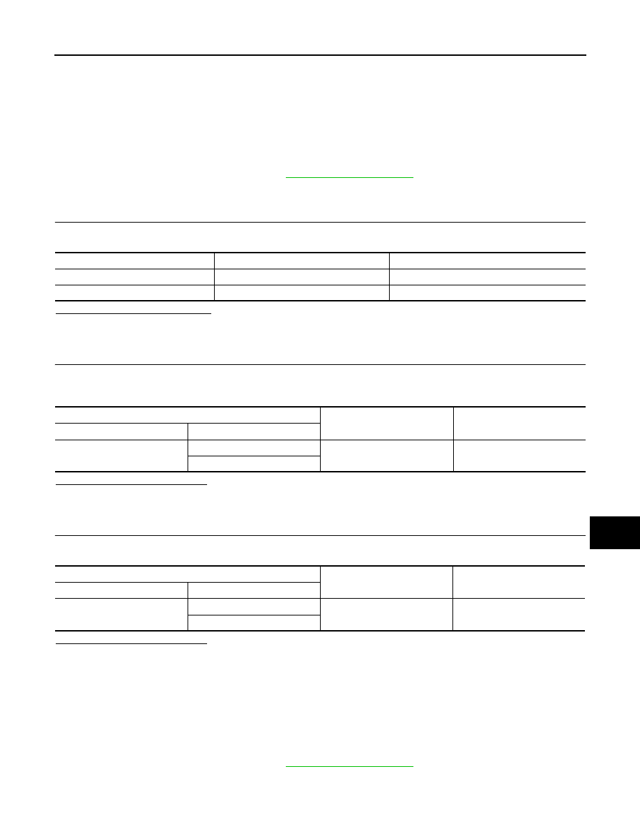
CHECK FUSE AND FUSIBLE LINK
Check that the following fuse and fusible link are not blown.
Is the fuse or fusible link blown?
YES
>> Replace the blown fuse or fusible link after repairing the affected circuit.
NO
>> GO TO 2
2.
CHECK POWER SUPPLY CIRCUIT
1. Disconnect BCM connector M81.
2. Check voltage between BCM connector M81 terminals 131, 139 and ground.
Is the inspection result normal?
YES
>> GO TO 3
NO
>> Repair or replace harness or connectors.
3.
CHECK GROUND CIRCUIT
Check continuity between BCM connector M81 terminals 134, 143 and ground.
Is the inspection result normal?
YES
>> Inspection End.
NO
>> Repair or replace harness or connectors.
IPDM E/R (INTELLIGENT POWER DISTRIBUTION MODULE ENGINE ROOM)
IPDM E/R (INTELLIGENT POWER DISTRIBUTION MODULE ENGINE ROOM) : Di-
agnosis Procedure
INFOID:0000000009764028
Regarding Wiring Diagram information, refer to
.
Terminal No.
Signal name
Fuse and fusible link No.
139
Fusible link battery power
O (40A)
131
BCM battery fuse
1 (10A)
BCM
Ground
Voltage
(Approx.)
Connector
Terminal
M81
131
—
Battery voltage
139
BCM
Ground
Continuity
Connector
Terminal
M81
134
—
Yes
143